
Lightweight, durable enclosures and laminates for making the same

Active Publication Date: 2010-11-18
WL GORE & ASSOC INC
View PDF22 Cites 13 Cited by
  • Summary
  • Abstract
  • Description
  • Claims
  • Application Information

AI Technical Summary

Benefits of technology

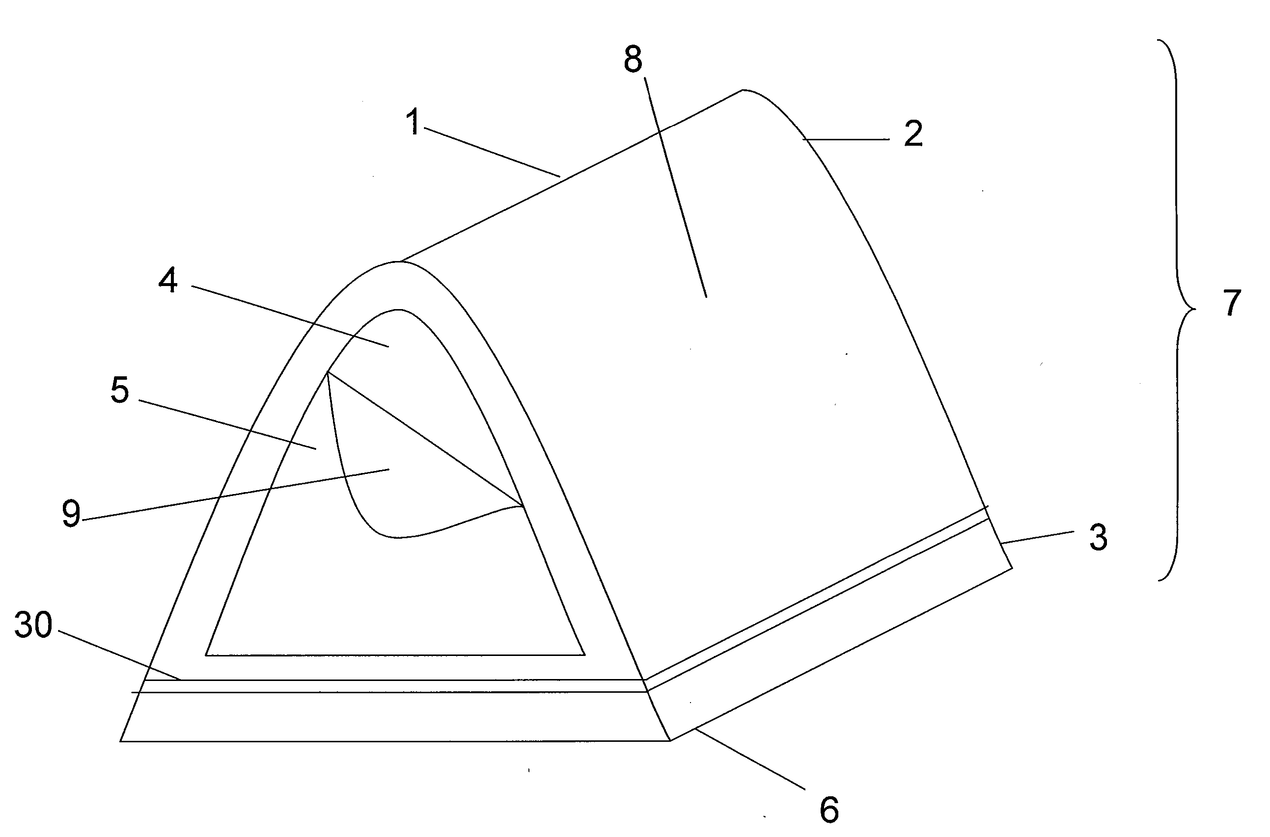
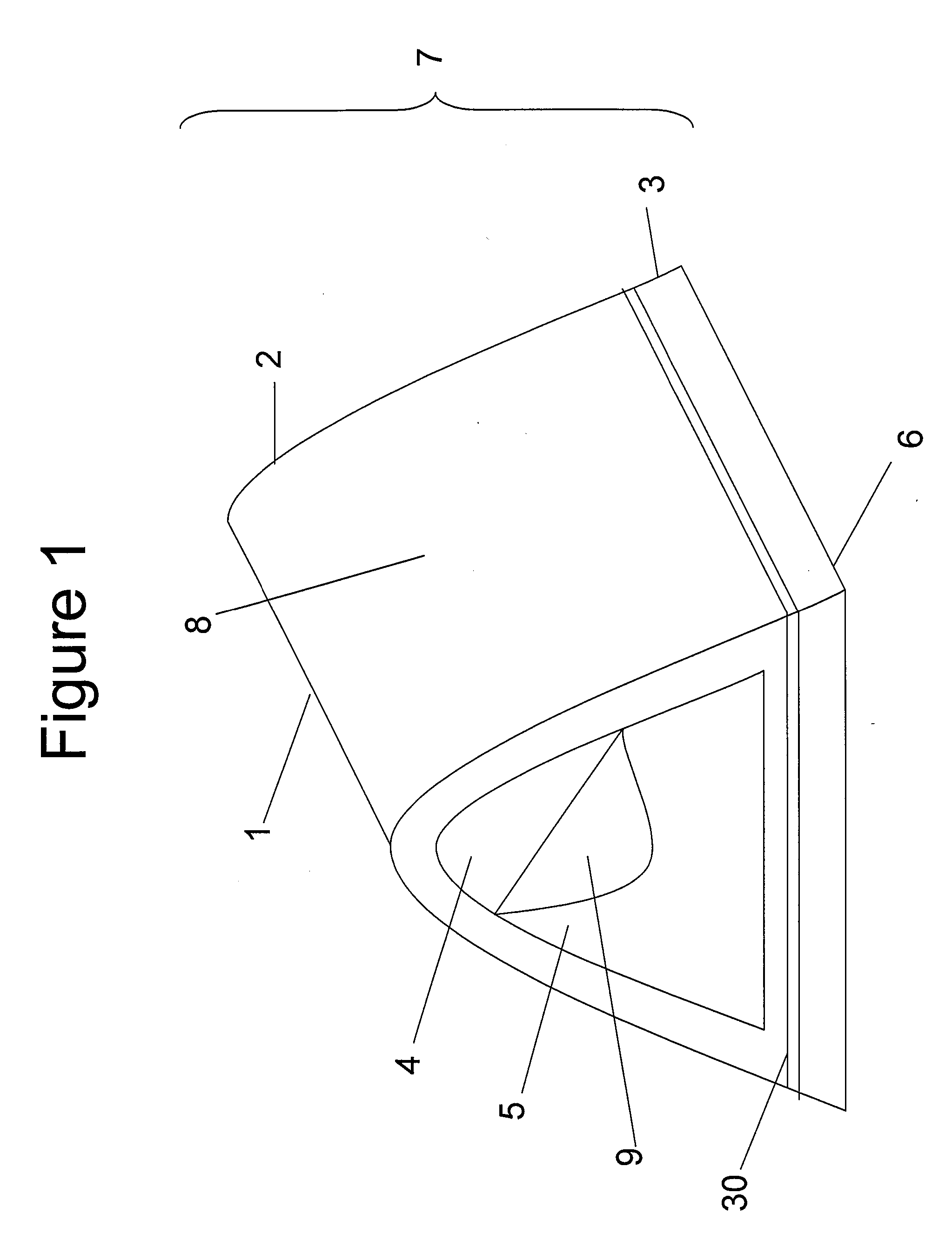
[0007]A lightweight enclosure is described that has an exterior film surface. The lightweight enclosure comprises an exterior film surface having properties such as abrasion resistance, thereby remaining durably liquidproof. The lightweight enclosure is formed from a laminate having sufficient oxygen permeability to sustain life while the enclosure openings are closed. A lightweight air permeable laminate is also described that comprises an outer film surface, and can be formed to have properties such as durable liquidproofness, flame resistance (passing CPAI-84), and can be colorized.

Problems solved by technology

However, the addition of the rain fly adds weight and bulk to the overall total construct.
Disadvantageously, coated materials fail to provide long-term waterproof durability.
Typical laminates used for single wall tents have many layers to insure long-term water resistance, but as a result, are heavy and have high water weight gain when rained upon thereby making them unsuitable for certain applications.
Moreover, the laminates of single wall tents are not air permeable and typically lack sufficient oxygen permeability to sustain the life of the occupants when the tent is closed, and often lack adequate flame resistance.
Coatings are frequently applied to enclosure materials to achieve flame resistance and UV stability; however, the coatings are susceptible to cracking in cold climates, as well as abrasion and other mechanical challenges that may induce failure.
Unfortunately, these meta-aramid textiles show significant deterioration of tensile strength after exposure to UV radiation, a common challenge in the field.
However, current lightweight single wall constructions using coated lightweight materials such as coated nylon, do not have long-term liquid resistance and do not reliably pass certain flame resistance requirements that are important to some tent users.
Single wall tents using materials that can achieve higher levels of flame resistance use multiple layers of higher weight fabric, adding bulk and weight to the construct.
Despite the description of the composite as lightweight, the composite fabric embodiments described disadvantageously have a weight reported to exceed 5.4 oz / yd2 making it too heavy and bulky for certain applications.

Method used


Image

  • Lightweight, durable enclosures and laminates for making the same
  • Lightweight, durable enclosures and laminates for making the same
  • Lightweight, durable enclosures and laminates for making the same

Examples


example 1

[0102]A three-layer laminate was formed comprising an outwardly facing printed outer film surface, a non-colorized inner film surface and a flame-resistant textile laminated between the two film layers.

[0103]The flame-resistant textile was a 1.5 oz / yd2 woven textile (1.7 denier per filament, cut to a staple length of 1.5″-2″ NOMEX Type 462 (93% NOMEX® aramid fibers, 5% Kevlar® aramid fibers, 2% P-140) Gore PN WCBZ000) with the tradename Nomex® Synergy Lite.

[0104]An expanded polytetrafluorethylene (PTFE) membrane was made from PTFE containing PFBE according to U.S. Pat. No. 6,541,589, and processed into an expanded membrane comprising polytetrafluoroethylene (PTFE) according to the process taught in U.S. Pat. No. 3,953,566. The microporous expanded PTFE membrane was water vapor and air permeable, and had the properties shown as Membrane Example 1 (M1) in Table 1.

[0105]The laminate was constructed as follows. One membrane was laminated to one side of the woven textile using a flame-re...

example 2

[0110]A three-layer laminate was formed comprising an outwardly facing outer film surface, an porous inner film, and a flame-resistant textile laminated between the two film layers, where both the outer and inner film surfaces were colorized with a black colorant.

[0111]Film layers were produced from microporous expanded PTFE membranes described in Example 1. Prior to lamination with a flame-resistant textile as described in Example 1, the surface of the porous membranes were rendered oleophobic by treating them with an aqueous latex of an organic polymer having pendant perfluoroalkyl side chains obtained from W. L. Gore & Associates, Inc. prepared based on Example 1B in U.S. Pat. No. 5,539,072 (incorporated herein by reference) and containing about 0.7% by weight of carbon black (Vulcan® XC72, Cabot Corporation, Boston, Mass). The resulting carbon coated membranes were dried at 200° C. After drying, the coated films had oil ratings of 6. The Gurley number of each sample was virtuall...

example 3

[0114]A three-layer laminate was formed comprising an outwardly facing printed outer film surface, an inner porous film colorized black, and a flame-resistant textile laminated between the two film layers.

[0115]Microporous membranes were made according to Example 1. One microporous expanded PTFE membrane layer was colorized black according to the method used Example 2 to form a colorized film layer. The colorized film was laminated to a flame resistant textile described in Example 1 to form a two-layer laminate. A second microporous membrane made according to Example 1 was laminated to the flame-resistant textile layer of the two-layer laminate to form a three-layer laminate. The black colorized film formed the porous inner film of the laminate.

[0116]The membrane surface on the side of the three-layer laminate opposite the black colorized film layer was printed with a desert camouflage pattern to form the laminate printed outer film surface. The outer porous film was printed accordi...


PUM

PropertyMeasurementUnit
Fractionaaaaaaaaaa
Weightaaaaaaaaaa
Volumeaaaaaaaaaa

Abstract

A lightweight enclosure is described that has an exterior film surface. The lightweight enclosure comprises a laminate having a porous outer film. The laminate is moisture vapor transmissive and flame resistance (passing CPAI-84), and abrasion resistance on the outer film surface thereby remaining durably liquidproof. The lightweight enclosure may be a single wall tent and is formed from a laminate having sufficient oxygen permeability to sustain life while enclosure openings are closed.

Description

FIELD OF THE INVENTION[0001]Described, herein, is a lightweight, air permeable enclosure having an exterior non-textile surface. Further described are lightweight laminates for making the enclosures.BACKGROUND OF THE INVENTION[0002]Lightweight enclosures that provide some protection from environmental conditions are known, such as tents, bivy bags, bivy sacks, and the like. Polyester and nylon materials used to construct lightweight enclosures are coated to provide water resistance or waterproofness, and can be printed to achieve a desired aesthetic.[0003]Lightweight tent constructions are typically considered as having either a double wall construction that has a separate rain fly and tent body, or a single wall construction having only a tent body comprised of, for example, a laminate material, and having no separate rain fly. Double wall tents rely on a rain fly to provide waterproofness by being positioned over a tent body otherwise constructed of highly air permeable and water ...

Claims


Application Information

Patent Timeline
IPC IPC(8): E04H15/54E04H15/32B32B5/32
CPCB32B5/18B32B5/32Y10T428/2481Y10T428/2835E04H15/54B32B5/022B32B5/024B32B5/026B32B5/08B32B5/22B32B5/30B32B7/14B32B27/08B32B27/12B32B27/14B32B27/322B32B2255/02B32B2255/04B32B2255/10B32B2255/20B32B2262/02B32B2262/0269B32B2262/0276B32B2262/04B32B2262/062B32B2262/101B32B2262/14B32B2264/0257B32B2307/3065B32B2307/4023B32B2307/50B32B2307/554B32B2307/558B32B2307/5825B32B2307/718B32B2307/72B32B2307/724B32B2307/7265B32B2307/734B32B2439/06B32B2439/46B32B2571/00Y10T442/3878Y10T428/249962Y10T428/24998Y10T442/2139
Inventor DWYER, MATTHEW J.
Owner WL GORE & ASSOC INC
Learn More