Sensor cartridge

a technology of sensor cartridges and cartridges, applied in the field of sensor cartridges, can solve the problems of requiring a lot of time and knowledge, requiring a lot of time and effort, and requiring a lot of time and effort, and achieve the effect of reducing the possibility of cross-reactions

Inactive Publication Date: 2010-11-18
KONINKLIJKE PHILIPS ELECTRONICS NV
View PDF4 Cites 16 Cited by
  • Summary
  • Abstract
  • Description
  • Claims
  • Application Information

AI Technical Summary

Benefits of technology

[0013]A sensor cartridge in accordance with embodiments of the present invention can be a replaceable or disposable (one-way) cartridge. The sensor cartridge according to embodiments of the present invention allows detecting the presence and / or determining the amount of at least two different target moieties in a same fluid sample substantially without cross-reaction of the different target moieties with different target homologues present at a sensor substrate surface negatively influencing the resulting sensor signal. Hence, the device and method according to embodiments of the invention show reduced cross-reactivity.
[0014]The sensor cartridge according to embodiments of the present invention shows a good sensitivity and is reliable and effective.
[0021]An advantage of the sensor cartridge according to embodiments of the present invention is that it may be used to simultaneously detect different target moieties present in a sample fluid without signals originating from cross-reaction disturbing the sensor signal.
[0022]The sensor cartridge may comprise control means for selectively releasing labelled magnetic or magnetizable objects from the at least first and second region in the reaction chamber. Preferably, the control means may be formed by a magnetic field generating means and may, for example, be formed by at least one current wire. By carefully steering the control means the magnetic or magnetizable objects may be controllably and selectively released from the first and second region and therefore, the possibility for cross-reactions to occur may be decreased.
[0040]An advantage of the method according to embodiments of the present invention is that different target moieties present in a sample fluid can be detected simultaneously without signals originating from cross-reactions disturbing the sensor signal.
[0041]According to embodiments of the invention, the method may furthermore comprise providing control means for selectively releasing labelled magnetic or magnetizable objects from the at least first and second region in the reaction chamber. According to embodiments of the invention, providing control means may comprise providing a control means for each of the at least first and second regions. By carefully steering the control means the magnetic or magnetizable objects may be controllably and selectively released from the first and second region and therefore, the possibility for cross-reactions to occur may be decreased.

Problems solved by technology

This optimisation is, however, a tedious process which is difficult to perform and which requires a lot of time and a lot of knowledge on different assays.

Method used


Image

  • Sensor cartridge
  • Sensor cartridge
  • Sensor cartridge

Examples


first embodiment

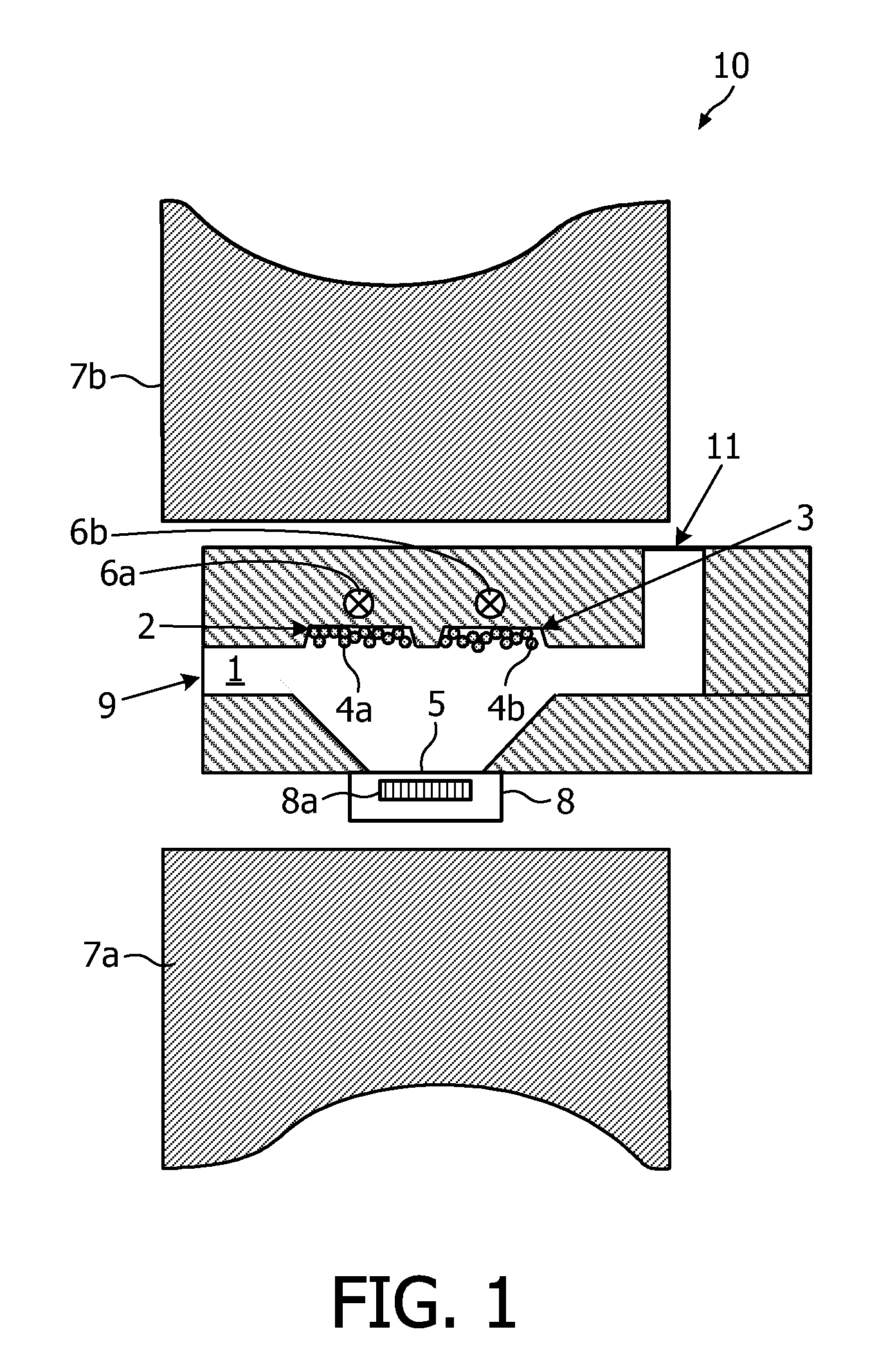
[0080]FIG. 1 illustrates a sensor cartridge 10 according to the present invention. The sensor cartridge 10 comprises a reaction chamber 1. The reaction chamber 1 is for receiving a sample fluid to be tested, the sample fluid comprising at least two different target moieties. The reaction chamber 1 may, according to this embodiment, comprise a first region 2 and a second region 3, the second region 3 being distinct from the first region 2. It is to be noted that the scope of the invention is not limited to only two distinct regions. Any number of regions larger than or equal to 2 is within the scope of the present invention. The first region 2 comprises a first type of magnetic particles, i.e. magnetic particles 4a labelled with a first type of probes (not shown) for specifically binding the magnetic particles 4a to a first type of target moieties and thus for specifically binding them to a first type of target homologues which may be present at the surface 5 of a sensor substrate 8....

second embodiment

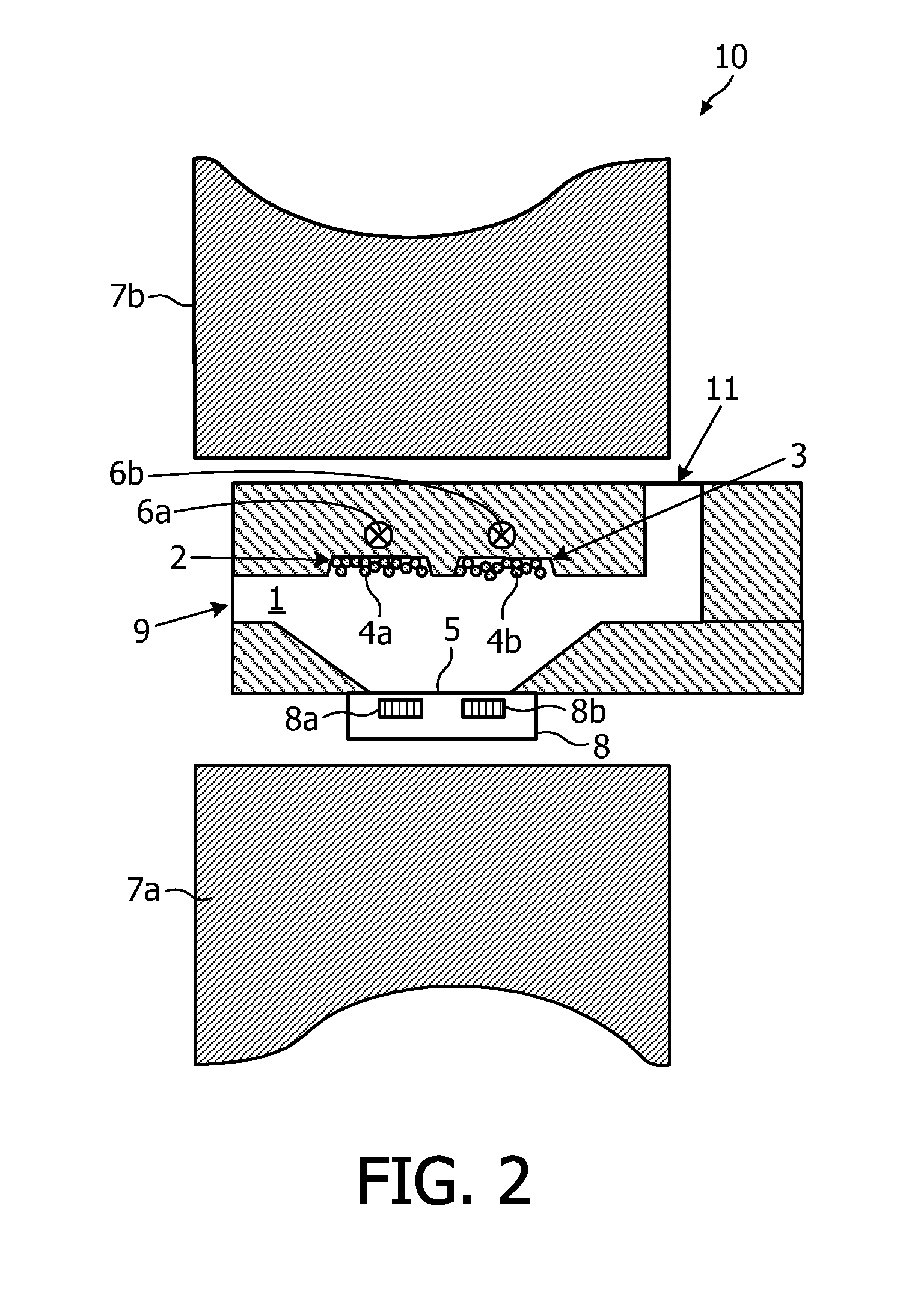
[0106]According to this second embodiment, cross-reaction may be reduced because the number of magnetic particles 4a, 4b that diffuse away from the corresponding sensor element 8a, 8b, . . . will be small.

diffusion length or distance x that a magnetic particle 4a, 4b travels in a certain time t is given by:

x=2Dtπ(1)

[0107]For example, a magnetic particle with a diameter of e.g. 300 nm may travel on average 10.5 μm due to Brownian motion.

[0108]Therefore, preferably, the distance between neighbouring regions 2, 3 may be between 10 μm and 1000 μm, more preferably between 50 μm and 500 μm and most preferably between 100 μm and 250 μm for particles with a diameter or size of 300 nm in samples with viscosity in the range of 1 mPa in order to avoid the first type of magnetic particles 4a to bind to the second GMR element 8a and vice versa (see further). It has to be noted that the diffusion length depends on the particle size and on the viscosity of the sample fluid. For example, when magne...

third embodiment

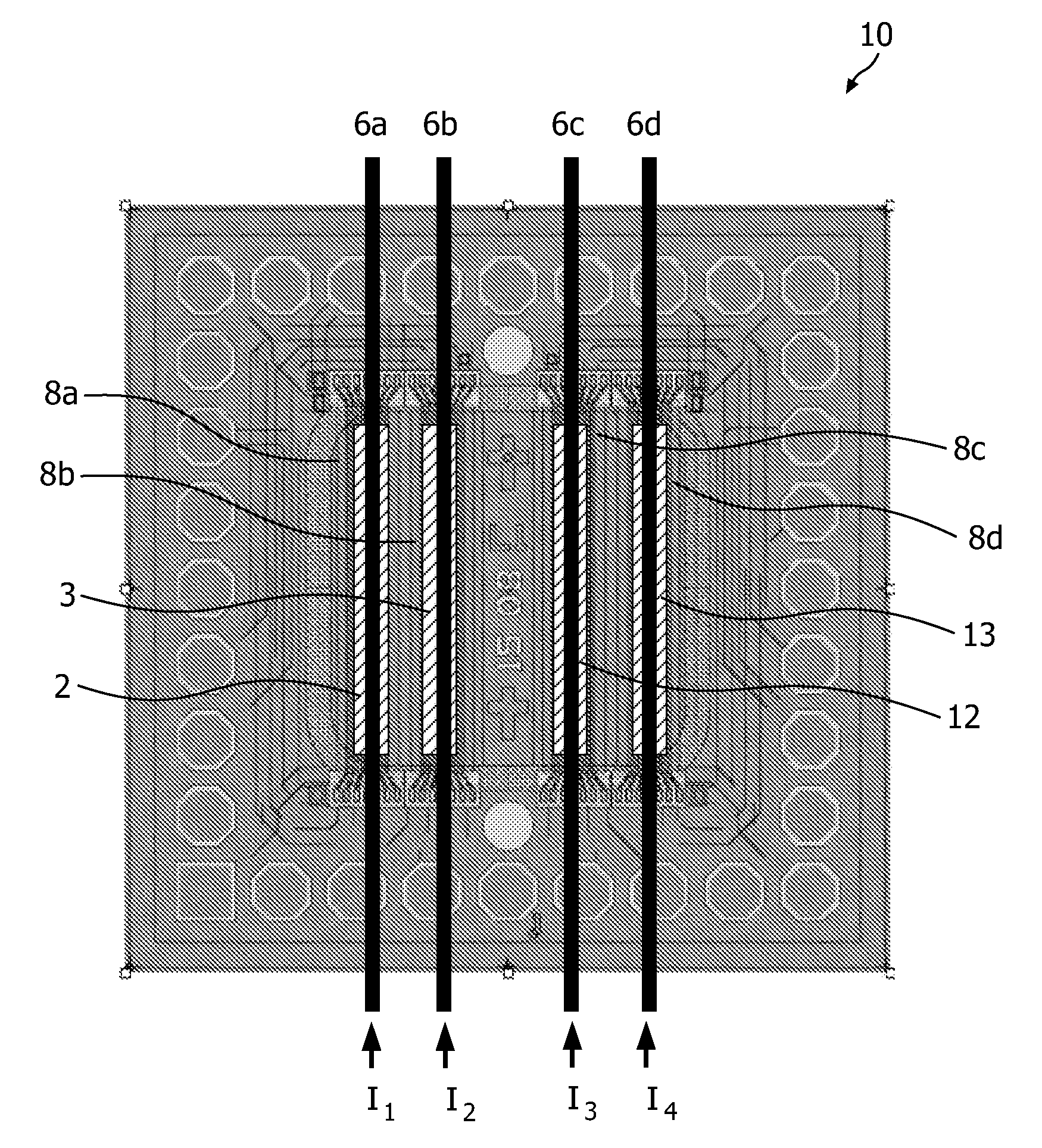
[0116]Distinct determination of the presence and / or amount of the first, second, . . . type of target moieties, according to this third embodiment, may be obtained by the presence of a control means for selectively releasing the first type of magnetic particles 4a, the second type of magnetic particles 4b, . . . from respectively the first region 2, the second region 3, . . . into the reaction chamber 1. This may be obtained by a control means, e.g. magnetic field generating means such as current wires, for selectively releasing the different types of magnetic particles 4a, 4b, 4c, 4d from their respective regions 2, 3, 12, 13. The current wires 6a-d needed for the selective release of magnetic particles 4a, 4b, 4c, 4d can also be used for actuation during the printing process. In this way, magnetic particles 4a, 4b, 4c, 4d can be transported to correct positions when the current wires 6a-d are activated during application of the magnetic particles 4a, 4b, 4c, 4d. The time between t...


PUM

PropertyMeasurementUnit
widthaaaaaaaaaa
lengthaaaaaaaaaa
sizeaaaaaaaaaa

Abstract

The present invention provides a sensor cartridge (10) for distinctively determining at least two different target moieties in a fluid sample. The sensor cartridge (10) comprises a reaction chamber (1) and at least a first and second region (2, 3) distinct from each other. The first region (2) comprises magnetic or magnetizable objects (4a) labelled with a first type of probes for specifically binding a first type of target moieties and the second region (3) comprises magnetic or magnetizable objects (4b) labelled with a second type of probes for specifically binding a second type of target moieties, the magnetic or magnetizable objects (4a, 4b) in the first and second region (2, 3) being directly contactable by the sample fluid. The present invention also provides a method for the manufacturing of such sensor devices (10) and a method for determining the presence and / or amount of at least two different target moieties in a sample fluid using such sensor cartridge (10).

Description

FIELD OF THE INVENTION[0001]The present invention relates to sensor cartridges, e.g. replaceable or disposable cartridges. More particularly, the present invention relates to sensor cartridges which can distinctively detect at least two different target moieties in a sample fluid. The present invention furthermore relates to a method for manufacturing such sensor cartridges and to a method for determining the presence and / or amount of at least two target moieties in a sample fluid. The device and methods according to embodiments of the invention can be used in molecular diagnostics, biological sample analysis or chemical sample analysis.BACKGROUND OF THE INVENTION[0002]Magnetic sensors based on AMR (anisotropic magneto resistance), GMR (giant magneto resistance) and TMR (tunnel magneto resistance) elements or on Hall sensors, are nowadays gaining importance. Besides the known high-speed applications such as magnetic hard disk heads and MRAM, new relatively low bandwidth applications...

Claims


Application Information

Patent Timeline
Patent Type & Authority Applications(United States)
IPC IPC(8): G01N27/74
CPCG01R33/1269
Inventor IMMINK, ALBERT HENDRIK JANDE THEIJE, FEMKE KARINAPRINS, MENNO WILLEM JOSEDITTMER, WENDY UYENNIEUWENHUIS, JEROEN HANS
Owner KONINKLIJKE PHILIPS ELECTRONICS NV
Why Eureka
Try Eureka