Optic film and backlight module using same

a backlight module and optic film technology, applied in the field of optic films, can solve the problems of high cost of backlight modules, substantial deterioration of performance in diffusing light, and high expense of optic films, and achieve excellent ductility, enhance the performance of optic films, and excellent rigidity.

Inactive Publication Date: 2010-11-18
GAMMA OPTICAL +1
View PDF4 Cites 2 Cited by
  • Summary
  • Abstract
  • Description
  • Claims
  • Application Information

AI Technical Summary

Benefits of technology

[0012]The primary purpose of the present invention is to overcome the drawback of the conventional optic film that comprises a diffusion layer containing diffusion beads that are hard to uniformly distributed through resin making the diffusion layer and easy to separate from the resin and also comprises a substrate that may have poor bonding capability, leading to unsecured bonding of prisms to a surface of the substrate.
[0013]Thus, an objective of the present invention is to provide an optic film that comprises a body and a condensation layer. The body is formed by stacking a plurality of substrates made of different materials. At least one of the substrates has a surface forming a light incidence surface of the body and another substrate has a surface forming a light emission surface of the body. The light incidence surface is treated by knurling or sand blasting to form a roughened frosted surface. The substrate that forms the light emission surface of the body is made of a material having excellent bonding capability to facilitate bonding thereof to the condensation layer. The substrate that forms the light incidence surface of the body is made of a material that exhibits excellent light diffusion characteristics to enhance diffusion of light transmitting therethrough.
[0014]Another objective of the present invention is to provide an optic film that comprises a body and a condensation layer. The body is formed by stacking a plurality of substrates made of different materials. The surface of the substrate that forms the light incidence surface of the body and the surface of the substrate that forms the light emission surface of the body are both treated by knurling or sand blasting to form a roughened frosted surface. With the light emission surface being treated to form a roughened frosted surface, when the condensation layer is positioned on the light emission surface, the bonding force between the condensation layer and the substrate can be enhanced, and light is subjected to secondary diffusion by the frosted surface of the light emission surface before the light is condensed by the condensation layer and leaving the optic film.
[0016]Yet a further objective of the present invention is to provide an optic film that comprises a body, which is formed by stacking a plurality of substrates of different materials. The body comprises a substrate that forms a light emission surface and a substrate that forms a light incidence surface and further comprises at least one intermediate substrate interposed between the previous two substrates. The intermediate substrate is made of a material that exhibits excellent rigidity, or excellent ductility, or any desired particular optic characteristics, in order to enhance the performance of the optic film. Yet a further objective of the present invention is to provide a backlight module, in which the optic film described above is embodied. With the body of the optic film being formed by stacking a plurality of substrates of different materials and further with the substrate that forms the light incidence surface being subjected to knurling or sand blasting to form a roughened frosted surface and further with a condensation layer arranged on the substrate of the body that forms the light emission surface, when light enters the body through the light incidence surface, the light is diffused first and is then subjected to condensation by the condensation layer, whereby the optic film realizes both diffusion and condensation of light and the optic film exhibits excellent optic performance due to the different characteristics of the different materials.

Problems solved by technology

The optic films are often of high expenses and this makes the costs of the backlight module very high and also leads to troubles and problems associated with complicated inventory of parts.
In addition, the diffusion beads 132 may also be subject to easy separation from the resin 131, leading to substantial deterioration of performance in diffusing light.
In case that the adhesion capability of the substrate 11 is poor, secured bonding of the prisms 12 to the surface of the substrate 11 will be negatively affected, leading to poor performance of light emission of a backlight module incorporating the optic film.

Method used


Image

  • Optic film and backlight module using same
  • Optic film and backlight module using same
  • Optic film and backlight module using same

Examples


Embodiment Construction

[0029]The following descriptions are of exemplary embodiments only, and are not intended to limit the scope, applicability or configuration of the invention in any way. Rather, the following description provides a convenient illustration for implementing exemplary embodiments of the invention. Various changes to the described embodiments may be made in the function and arrangement of the elements described without departing from the scope of the invention as set forth in the appended claims.

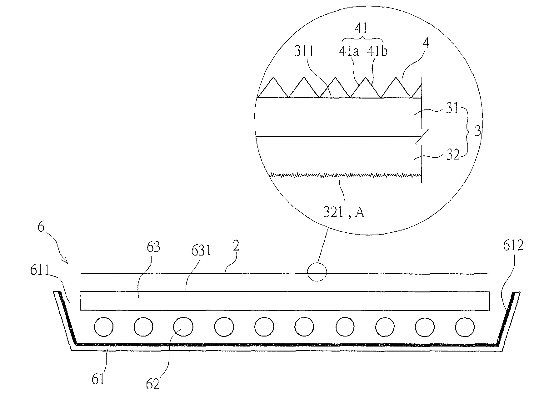
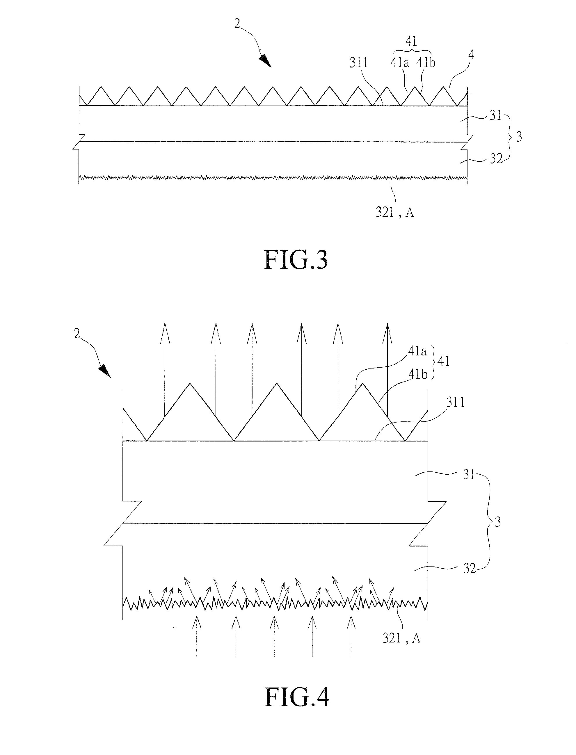
[0030]With reference to the drawings and in particular to FIG. 3, an optic film constructed in accordance with the present invention, generally designated with reference numeral 2, comprises a body 3 and a condensation layer 4. The body 3 is formed by stacking multiple layers of substrates 31, 32 that are made of different materials. In the embodiment illustrated, two layers of substrates are provided as an example for explanation. The substrates 31, 32 can be made of high-molecule materials or p...


PUM


Abstract

An optic film includes a body and a condensation layer. The body is formed by stacking a plurality of substrates made of different materials. By means of the different physical characteristics of the different materials, the optic film realizes excellent optic performance. Also provided is a backlight module using the optic film.

Description

CROSS-REFERENCE TO RELATED APPLICATION[0001]This is a division of the co-pending patent application Ser. No. 12 / 193,763, filed Aug. 19, 2008.BACKGROUND OF THE INVENTION[0002](a) Technical Field of the Invention[0003]The present invention relates to an optic film, and in particular to an optic film having a body formed by stacking multiple substrates to effect both diffusion and condensation of light and to be applicable to a backlight module.[0004](b) Description of the Prior Art[0005]A thin-film transistor liquid crystal display (TFT-LCD) comprises a light source that is provided by a backlight module. The backlight module must provide light of excellent uniformity and brightness in order to ensure excellent subsequent applications and uses.[0006]The backlight module uses various numbers of optic films, which include a diffusion film for diffusion of light and a prism film that condenses light. The number and arrangement of the optic films can be varied as desired.[0007]The optic f...

Claims


Application Information

Patent Timeline
Patent Type & Authority Applications(United States)
IPC IPC(8): F21V7/22
CPCG02B5/0242G02B5/0278G02F2001/133607G02B6/0053G02B6/0055G02B6/0036G02F1/133607
Inventor MAI, CHIEN-CHINYIN, JUI-TANGWANG, YEONG-FENG
Owner GAMMA OPTICAL
Why Eureka
Try Eureka