Vertical cable management system

a management system and cable technology, applied in the direction of cables, insulated conductors, instruments, etc., can solve the problems of increasing the volume of empty space to be shipped, increasing the volume of cable managers to be shipped, and increasing shipping costs

Active Publication Date: 2010-11-18
PANDUIT
View PDF54 Cites 10 Cited by
  • Summary
  • Abstract
  • Description
  • Claims
  • Application Information

AI Technical Summary

Benefits of technology

[0009]Also, the electronic equipment that is typically mounted to an equipment rack, such as patch panels and power strips, generate heat, requiring that thermal management for these devices be designed into the cable manager. Proper ventilation ports in the cable manager can assist in allowing air circulation in and out of the cable manager.

Problems solved by technology

The package including the cable manager includes a substantial volume of empty space between the members forming the cable manager, which increases the shipping cost to transport the volume of empty space.
In some cable managers, the fingers are fixedly mounted on the cable manager structure, which increases the volume of the cable manager to be shipped, thus increasing shipping costs.
Further, present cable managers are not configured to utilize the cable manager to mount additional EIA-310 standard dimension electronic or other equipment to the cable manager, thus limiting the capacity of the telecommunications system.
In typical cable managers, the space between the side panels that support the fingers is underutilized because the cross brace brackets supporting the cable manager are randomly spaced and unable to act as mounting supports for EIA-310 dimensioned equipment.
Also, present cable managers do not define a separate vertical pathway for the small number of fiber cables routed from an enclosure compared to the large number of copper cables routed from the patch field of high density switch applications of a telecommunications system.

Method used


Image

  • Vertical cable management system
  • Vertical cable management system
  • Vertical cable management system

Examples


second embodiment

[0109]FIG. 42 illustrates the side panel 22 of the cable manager 10, with two embodiments of ventilation apertures through side panel 22. In one embodiment, the ventilation perforations comprise a plurality of apertures 192 spaced close together to provide ventilation in and out of volume 136 of cable manager 10. The opposite side wall 24, not shown, is similarly perforated. In ventilation perforations shown in FIG. 42, the perforations comprise a plurality of close-together U-shaped cutouts or apertures 194 extending through side panel 22. Each aperture 194 includes a tongue portion 196 extending into the center of each aperture 194. The tongue portions 196 also allow for cable tie-offs. The opposite side wall 24, not shown, also includes U-shaped apertures 194 for ventilation.

third embodiment

[0110]FIG. 43 also illustrates side panel 22 of cable manager 10, with two additional embodiments of ventilation apertures through side panel 22. In a third embodiment, the ventilation embodiment comprises rectangular cutouts 198 extending through side panel 22. In this embodiment, it is preferable that rectangular cutouts 198 in cable manger 10 be aligned with rectangular cutouts 188 in component rack 12 (FIG. 41) to provide the proper ventilation. The opposite side wall 24, not shown, also includes similarly located rectangular cutouts 198 for ventilation.

fourth embodiment

[0111]FIG. 43 additionally illustrates ventilation apertures extending through side panel 22 and opposing side panel 24, (not shown) of cable manager 10. In this embodiment, multiple pass-through apertures 200 are placed close together on side panel 22 to provide strength or rigidity and proper ventilation. The proximity of each aperture 200 also creates additional tie-off options for securing cables 128, 132 to the cable manager 10.

[0112]The various ventilation options shown in FIGS. 42 and 43 may be used alone, or combined in various layouts to provide appropriate ventilation. In addition, it is also preferable that apertures 192 (FIG. 42), U-shaped apertures 194 (FIG. 42) and pass through apertures 200 (FIG. 43) be aligned with rectangular cutouts 188 in component rack 12 (FIG. 41).

[0113]In certain embodiments of the present invention, cable manager 10 includes door brackets 200a (FIG. 38) or 200b (FIG. 44), which are removably connected to side panels 22 and 24. For example, as ...


PUM

PropertyMeasurementUnit
rotationaaaaaaaaaa
distanceaaaaaaaaaa
distanceaaaaaaaaaa

Abstract

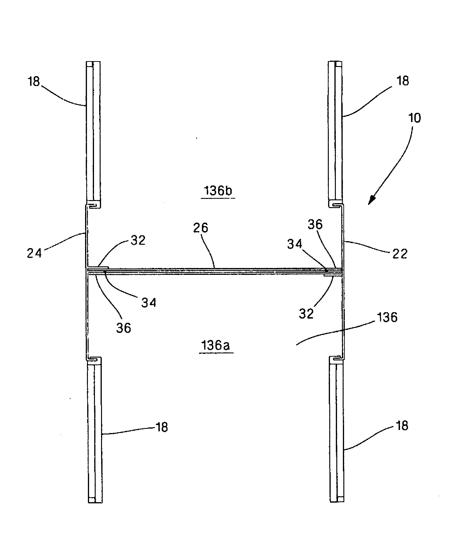
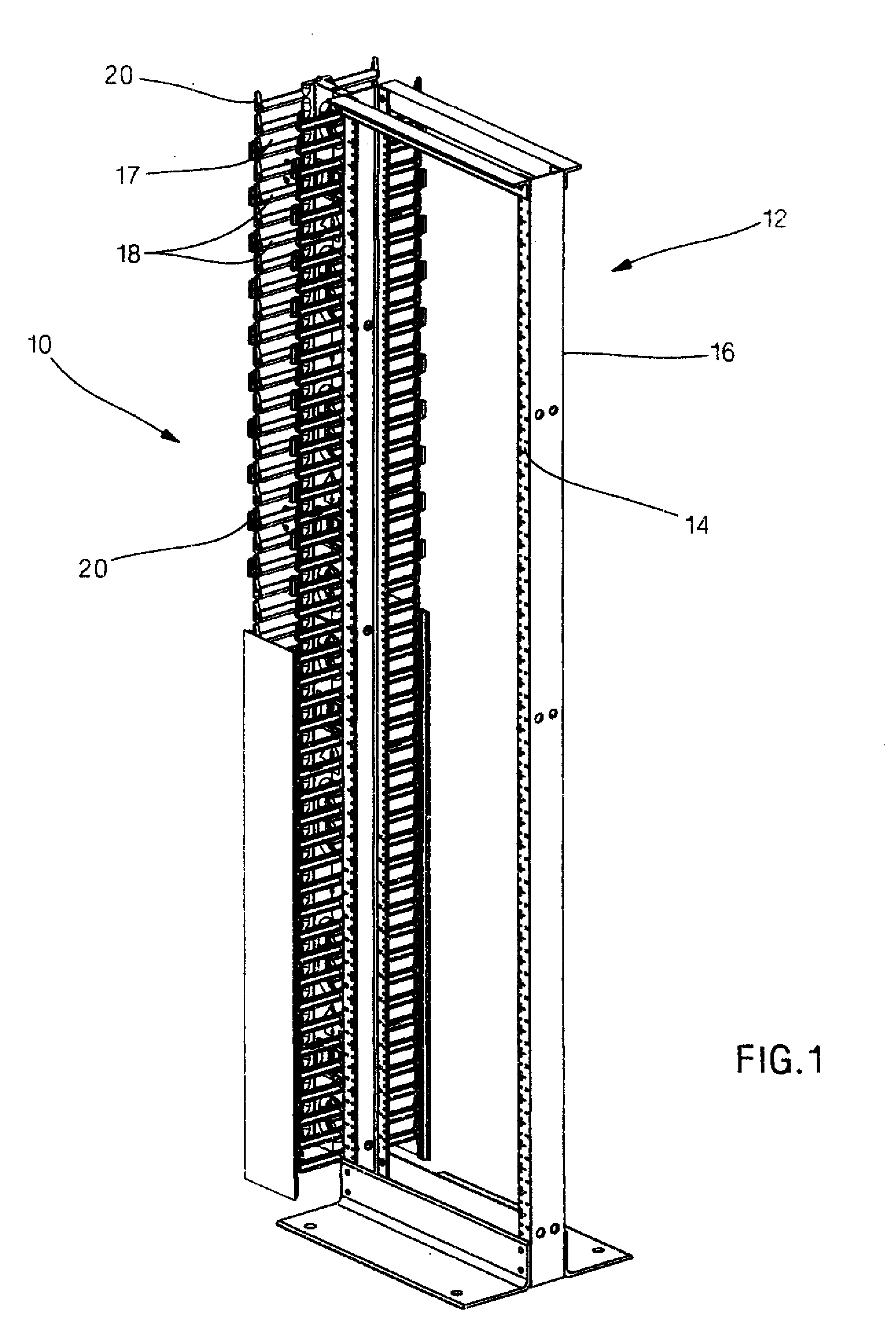
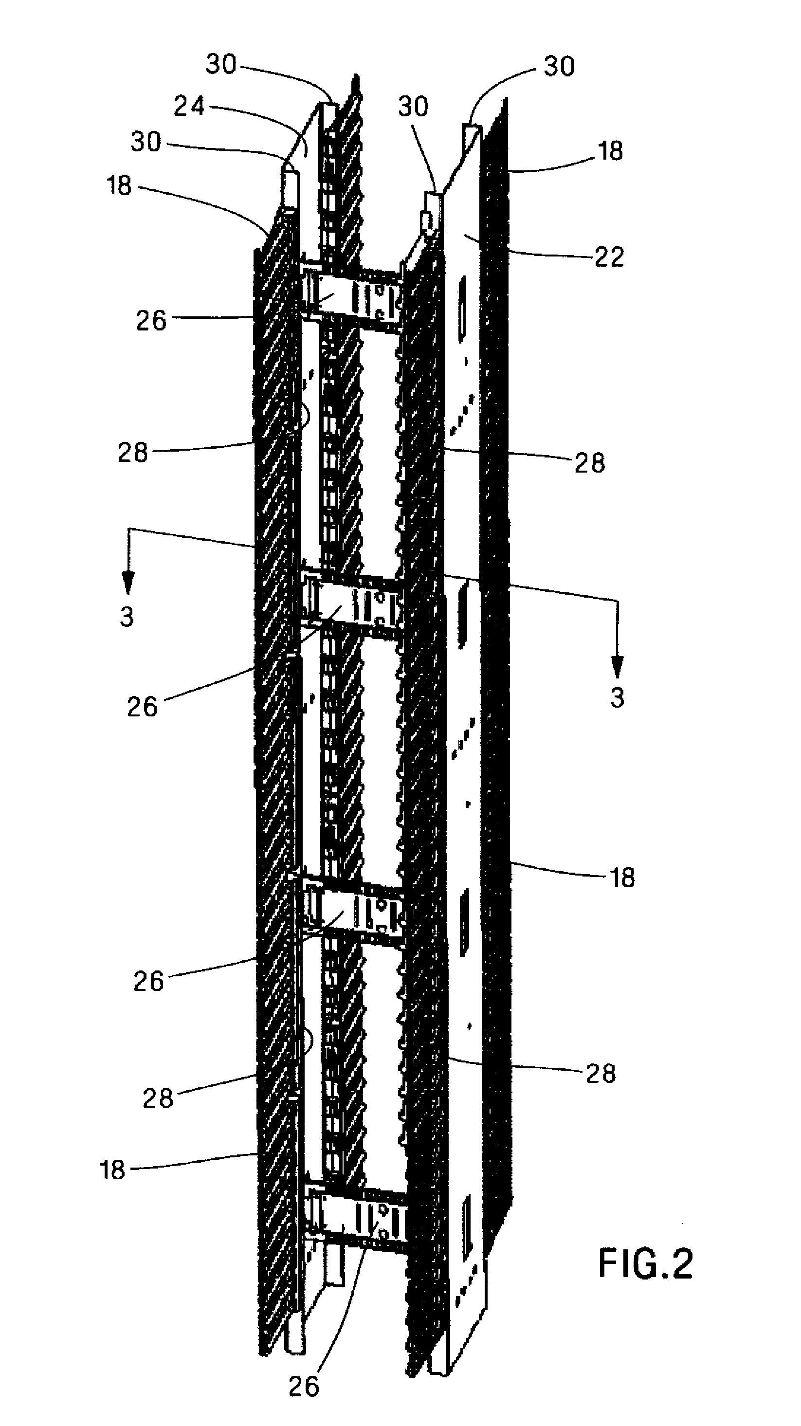
Certain embodiments of the present invention provide a cable manager. The cable manager includes a first side panel, a second side panel spaced apart from the first side panel, a first cross brace bracket connected to the first side panel and the second side panel, and a second cross brace bracket connected to the first side panel and the second side panel and spaced apart from the first cross brace bracket. The first side panel, the second side panel, the first cross brace bracket, and the second cross brace bracket define a first cable pathway for routing a first plurality of cables and a second cable pathway for routing a second plurality of cables.

Description

CROSS-REFERENCE TO RELATED APPLICATIONS[0001]This application claims priority to U.S. Provisional Application No. 61 / 147,531, filed Jan. 27, 2009, the subject matter of which is hereby incorporated by reference in its entirety.FIELD OF THE INVENTION[0002]Generally, this invention relates to cable management devices for communications network equipment racks. In particular, this invention relates to an improved vertical cable manager for managing copper cables and fiber cables.BACKGROUND[0003]Cable managers are known for routing the wires and cables of electronic equipment, such as telecommunications equipment and computers. These wires and cables include UTP, ScTP, coaxial and fiber optic cables capable of transmitting data, voice, video and / or audio information. Network equipment racks are known to support the electronic equipment and patch panels in a telecommunications system. Cable managers are typically used in association with the equipment racks to receive and route the wires...

Claims


Application Information

Patent Timeline
Patent Type & Authority Applications(United States)
IPC IPC(8): G02B6/00H01B7/00
CPCH04Q1/035H04Q1/062H04Q1/023H04Q1/021
Inventor NEWMAN, DAVID P.FRITZ, ROBERT L.EVANS, JR., STANLEY P.KROMENAKER, CLARK M.GLEGHORN, NATHAN A.
Owner PANDUIT
Why Eureka
Try Eureka