Bioelectric implant and method

a bioelectric implant and implant technology, applied in the field of bioelectric implants, can solve the problems of increasing the cost of orthopedic implants, and limiting so as to improve the ability of implants to stabilize bone and tissue healing.

Inactive Publication Date: 2010-11-18
INGENIUM
View PDF55 Cites 36 Cited by
  • Summary
  • Abstract
  • Description
  • Claims
  • Application Information

AI Technical Summary

Benefits of technology

[0015]In accordance with the present invention, bioelectric implants and methods are provided to include orthopedic fixation devices in the form of bi

Problems solved by technology

While it may be well known to provide a source of electrical power for enhancing tissue healing/regeneration, dedicated devices for generating electrical potential add to the overall cost and complexity of an orthopedic implant procedure.
Furthermore, with respect to implanted batteries, the increased cost of using such batteries also results in a greater invasive procedure because the batteries must be separately implanted and monitored over time.
As orthopedic procedures continue t

Method used


Image

  • Bioelectric implant and method
  • Bioelectric implant and method
  • Bioelectric implant and method

Examples


first embodiment

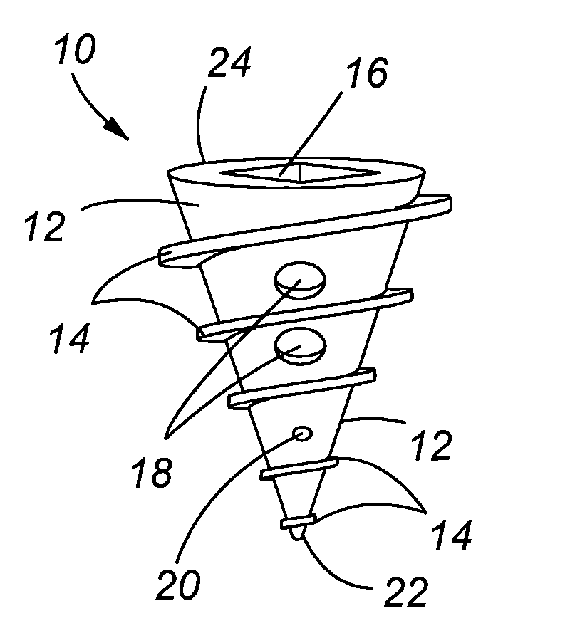
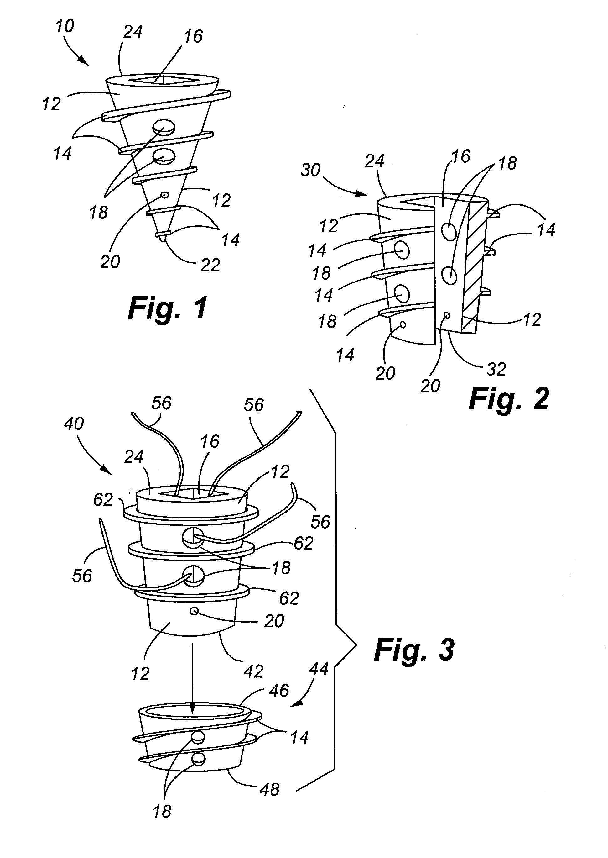
[0041]FIG. 1 illustrates the bioelectric implant 10 of the present invention. The bioelectric implant 10 is characterized by a body 12 which comprises the cathode portion, and a central opening 16 that is coated with a dissimilar metal, thereby forming an anode portion. Preferred materials for the cathode may include titanium, steel, cobalt, molybdenum, metal oxides, or alloys thereof. Preferred materials for the anode portion may include magnesium, zinc, or alloys thereof.

[0042]The first embodiment is further characterized as having a larger end 24, and a smaller end or tip 22. The embodiment of FIG. 1 shows the body 12 having a substantially conical shape; however, it shall be understood that the particular shape of the body 12 may be modified for the intended use of the implant. For example, the body 12 could be cylindrical shaped, and further, instead of the tip 22 being closed, it is contemplated that the central opening 16 could extend completely through the body, thereby resu...

second embodiment

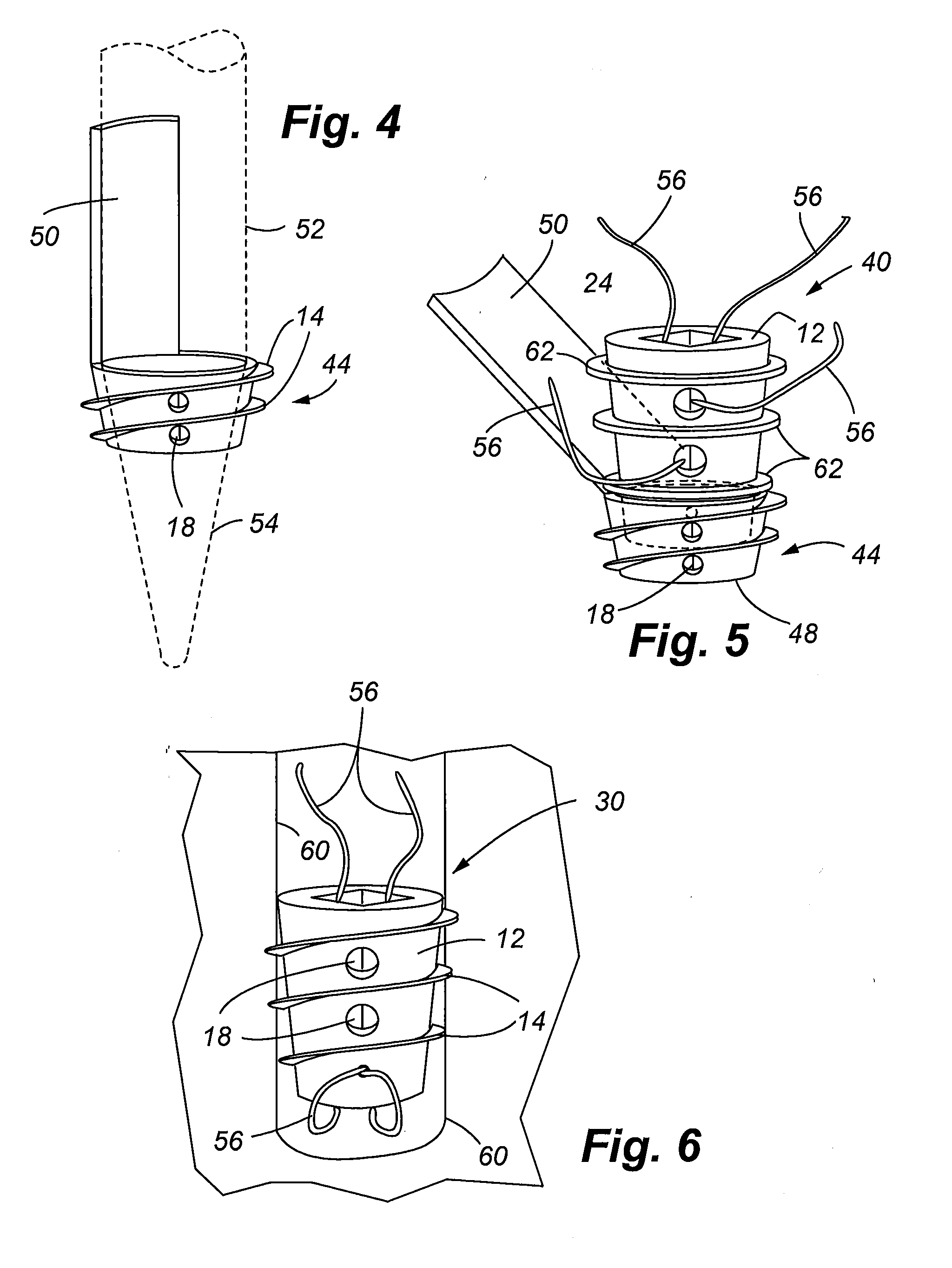
[0045]FIG. 3 illustrates yet another preferred embodiment of an implant 40 of the present invention, like reference numbers in this embodiment also denoting the same structural features found in the prior embodiments. The implant 40 in this embodiment has two components or parts, namely, a distal lock ring 44, and a body 12 which resembles the body 12 in the embodiment of FIG. 2. However in this second embodiment, the body 12 incorporates a plurality of ribs 62 as opposed to threads 14. The ribs 62 are used to lock the body 12 in the distal locking ring 44. The ribs also serve as anchoring features. The locking ring 44 is connected to the body 12 to form a single larger implant. The body 12 includes the truncated end 42 which frictionally engages the receiving end 46 of the distal lock ring as by contact of one or more ribs 62 that are received within the central opening of the locking ring 44. The conical shape of the body 12 may be adjusted to provide contact with the desired numb...


PUM


Abstract

Bioelectric implants are provided in three distinct embodiments, namely a bone/tissue anchor, a suture construction, and a plate. The bioelectric implants function in dual capacities as both fixation devices, and as galvanic cells for the production of electrical energy used for therapeutic purposes in tissue regeneration and healing. The bioelectric anchor may take the general form of a screw or pin having a hollow interior or cavity that extends through the body of the anchor. A coating can be applied to the cavity to form the anode portion of the galvanic cell. The outer surface of the anchor serves as a cathode. Bodily fluids and tissue act as an electrolyte to facilitate the chemical reactions necessary for the galvanic cell. For the suture construction, one or more strands of material are the cathode, and one or more strands of peripheral surrounding material act as the anode. Bodily fluids/tissue in contact with the suture act as an electrolyte. The bioelectric plate can be used in combination with the bioelectric anchor to supplement delivery of electrical energy. The plate has anode and cathode portions also making it a source of electrical energy.

Description

FIELD OF THE INVENTION[0001]The present invention relates generally to medical methods and apparatuses for repair and stabilization of damaged tissues, and more particularly, to orthopedic fixation implants that generate electrical energy to provide therapeutic benefits for healing of the affected tissues.BACKGROUND OF THE INVENTION[0002]It is well known to utilize a source of electrical power in order to speed the healing process in damaged bone and soft tissue. Through extensive research and development, it has been found that both electrical current and magnetic fields can play an important role in modifying tissue behavior. It is known that bone tissue generates its own electrical potentials during the healing process, and exposing the bone tissue to electrical energy at selected voltages and amperages can greatly enhance the speed of tissue regeneration.[0003]Accordingly, a number of references disclose electrical implants that are used for various healing and regenerative purp...

Claims


Application Information

Patent Timeline
IPC IPC(8): A61N1/05
CPCA61N1/326
Inventor SCHNEIDER, DAVID J.
Owner INGENIUM
Why Eureka
Try Eureka