Car navigation system

a technology for navigation systems and cars, applied in navigation instruments, surveying and navigation, instruments, etc., can solve the problems of increasing the measurement error of the attitude angle (pitch angle in particular), reducing the detection accuracy of the position and heading angle of the vehicle, and detecting the yaw rate improperly, etc., to achieve the effect of higher accuracy

Active Publication Date: 2010-11-18
MITSUBISHI ELECTRIC CORP
View PDF5 Cites 21 Cited by
  • Summary
  • Abstract
  • Description
  • Claims
  • Application Information

AI Technical Summary

Benefits of technology

[0025]According to the car navigation system in accordance with the present invention, since it can determine the yaw direction mounted angle of the casing in the body, it ca

Problems solved by technology

For example, when the vehicle makes a turn while running along a slope or makes a high-speed horizontal turn, since the output signal of the acceleration sensor changed by the effect of the lateral acceleration is detected as the effect of the road slope angle, the measuring error of the attitude angle (pitch angle in particular) of the vehicle increases.
Accordingly, it is very likely that improper correction of the yaw rate detected by the angular velocity sensor or of the distance of vehicle movement (velocity) detected by the distance sensor occurs, which will bring about reduction in the detection accuracy of the position and heading angle of the vehicle.
Accordingly, they incorrectly detect variations in the XB axis acceleration due to the

Method used


Image

  • Car navigation system
  • Car navigation system
  • Car navigation system

Examples


embodiment 1

[0038]FIG. 4 is a block diagram showing a configuration of a car navigation system of an embodiment 1 in accordance with the present invention centering on a portion relating to body attitude measurement. The car navigation system comprises an angular velocity sensor 1, a distance sensor 2, an acceleration sensor 3 and a signal processing unit 4, which are placed in a car navigation casing.

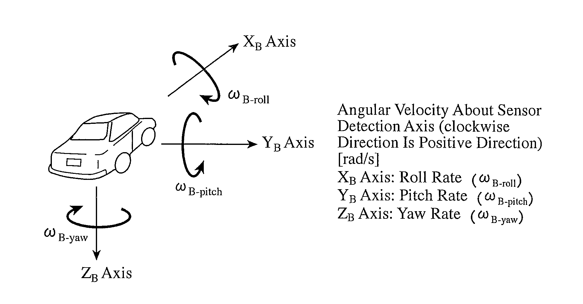
[0039]The angular velocity sensor 1 is composed of a gyrocompass, for example, and detects a yaw rate, which is the angular velocity having the sensor detection axis in the vertical direction of the casing, at every prescribed period. A signal corresponding to the angular velocity (yaw rate) output from the angular velocity sensor 1 is delivered to the signal processing unit 4. The distance sensor 2 outputs a pulse signal corresponding to the distance of vehicle movement by the vehicle. The pulse signal output from the distance sensor 2 is delivered to the signal processing unit 4. The acceleratio...

embodiment 2

[0066]The car navigation system of the foregoing embodiment 1 is configured in such a manner as to perform the detection of the mounted angle in the body and the correction of the body attitude when the casing is set in the body with a rotation in the yaw direction. In contrast, the car navigation system of the embodiment 2 is configured in such a manner as to perform the detection of the mounted angle in the body and the correction of the body attitude when the casing is set in the body with a tilt in the pitch direction. In the following, the description of the same portions as those of the embodiment 1 is omitted or simplified centering on the description of different portions.

[0067]FIG. 6 is a block diagram showing a configuration of the car navigation system of the embodiment 2 in accordance with the present invention centering on portions relating to the body attitude measurement. The car navigation system is configured by replacing the yaw direction mounted angle detecting un...

embodiment 3

[0084]The car navigation system of the foregoing embodiment 1 is configured in such a manner as to perform the detection of the mounted angle in the body and correction of the body attitude when the casing is set in the body with a rotation in the yaw direction, and the car navigation system of the embodiment 2 is configured in such a manner as to perform the detection of the mounted angle in the body and correction of the body attitude when the casing is set in the body with a tilt in the pitch direction. In contrast, the car navigation system of the embodiment 3 is configured in such a manner as to perform the detection of the mounted angle in the body and correction of the body attitude when the casing is set in the body with a rotation in the yaw direction and with a tilt in the pitch direction. In the following, description of the same portions as those of the embodiment 1 and embodiment 2 is omitted centering on the description of different portions.

[0085]FIG. 8 is a block dia...


PUM


Abstract

A car navigation system includes a distance sensor 2; an angular velocity sensor 1 for detecting angular velocity having a sensor detection axis in a vertical direction of a casing; an acceleration sensor 3 for detecting acceleration having a sensor detection axis in a back and forth direction of the casing on a horizontal plane; a body velocity and acceleration measuring unit 42 for measuring velocity and acceleration in the body direction of vehicle movement from the signal from the distance sensor; an angular velocity measuring unit 41 for measuring angular velocity from the signal from the angular velocity sensor; a body roll angle estimating unit 43 for estimating a body roll angle from the body direction of vehicle movement velocity and angular velocity; an acceleration sensor output estimating unit 45 for outputting, when the casing is set in the body with a rotation in a yaw direction, estimation values of the output signal of the acceleration sensor at every prescribed angle; and a yaw direction mounted angle detecting unit 46 for determining as a yaw direction mounted angle in the body an angle at a time when an estimated value is obtained which agrees most closely with a value remaining after subtracting from the signal from the acceleration sensor its offset component.

Description

TECHNICAL FIELD[0001]The present invention relates to a car navigation system for measuring, when a vehicle is moving along a road including slopes, its quantity of motion associated with its body attitude such as an inclination angle, angular velocity, velocity or acceleration, and particularly to a technique for measuring the body attitude accurately by correcting effect of the remaining axes on the output of the sensor even when the casing of the car navigation system is set in the car body in such a manner that the sensor detection axes are askew.BACKGROUND ART[0002]Conventionally, in a car navigation system, to improve the detection accuracy of the current position and heading angle of the vehicle, a contrivance is made for obtaining on a horizontal plane the variance of the heading angle of vehicle movement and distance of vehicle movement (velocity) more accurately.[0003]For example, as for a vehicle position detecting device disclosed in Patent Document 1, to eliminate a pro...

Claims


Application Information

Patent Timeline
IPC IPC(8): G01C21/16
CPCG01C21/26
Inventor ISHIGAMI, TADATOMIFUJII, MASATOSHIKUMAGAI, SHIGEKIKAN, KEIKAOUCHI, SADAMIKATO, HIROAKI
Owner MITSUBISHI ELECTRIC CORP
Why Eureka
Try Eureka