Eureka AIR delivers breakthrough ideas for toughest innovation challenges, trusted by R&D personnel around the world.

Fuel injector the control valve element of which has a support region

a technology of injector and control valve, which is applied in the field of injector, can solve the problems of linear sealing edge burden and inconsiderable wear, and achieve the effect of ensuring manufacturing precision of sealing line and good results

Active Publication Date: 2010-11-25
ROBERT BOSCH GMBH
View PDF11 Cites 4 Cited by
  • Summary
  • Abstract
  • Description
  • Claims
  • Application Information

AI Technical Summary

Benefits of technology

[0003]It is the object of the invention to propose an injector with a control valve that is at least approximately pressure-balanced in the axial direction, and in which the wear at the sealing line of the control valve element is reduced.Technical Solution
[0005]The invention is based on the concept of increasing the stability, that is, the invulnerability to wear, of the control valve element by providing that a support region, which extends in the radial direction past the sealing line into the high-pressure region of the injector, which region, when the control valve is open, communicates with the low-pressure region of the injector in order to bring about a rapid pressure drop in the control chamber of the injector, which in turn results in an opening motion of the injection valve element, is associated with the approximately linear control valve element sealing edge (sealing line) that in the closed position of the control valve rests in sealing fashion on a control valve seat. In other words, in an injector embodied in accordance with the concept of the invention, the control valve element is bounded, in the radial direction toward the pressure chamber, not by the sealing edge but by a support region adjoining the sealing line. Because the invention provides a support region, the impact impetus with which the control valve element strikes the control valve seat associated with it is distributed more uniformly in the control valve, and in particular in the control valve element, and as a consequence leads to lesser component stresses. This in turn results in increased stability of the control valve element, with the positive consequence that wear phenomena of the sealing line over the service life of the injector are minimized.
[0008]To minimize the effects on the pressure-balanced property of the control valve of unavoidable sealing line wear, an embodiment of the injector in which the high-pressure angle left open is greater than the low-pressure angle left open of the control valve is advantageous. The high-pressure angle left open is the angle, located in the high-pressure region, between the boundary line, adjoining the sealing line, of the support region or of the control valve element, and the control valve seat face. The low-pressure angle left open is the angle, located in the low-pressure region of the injector, between the (lower) boundary line of the control valve element and the control valve seat face.
[0010]To make it possible to ensure manufacturing precision of the sealing line in an injector, embodied in accordance with the concept of the invention, at feasible expense, an embodiment is preferred in which the control valve element angle, which is defined by the two radially extending boundary lines, adjoining the sealing line, of the control valve element, and the control valve seat angle are not the same. Especially preferably, the difference in angles amounts to more 10°, and especially preferably more than 20°. Especially good results in terms of the manufacturing precision of the sealing line can be expected at a difference between angles in a range between approximately 30° and approximately 60°. Ideally, the control valve seat angle is greater than the control valve element angle. By the provision of a difference in angles as described above between the control valve element angle and the control valve seat angle, on the one hand there is a sufficiently great support action of the support region, and on the other, exact production of the sealing line (sealing edge) becomes possible. To increase the support action (at the expense of exact production capability), a smaller difference between angles can also be selected.

Problems solved by technology

A disadvantage of the known injector is the heavy burden on the linear sealing edge upon closure of the control valve, which can lead to not inconsiderable wear at the sealing line.

Method used


Image

  • Fuel injector the control valve element of which has a support region
  • Fuel injector the control valve element of which has a support region
  • Fuel injector the control valve element of which has a support region

Examples


Embodiment Construction

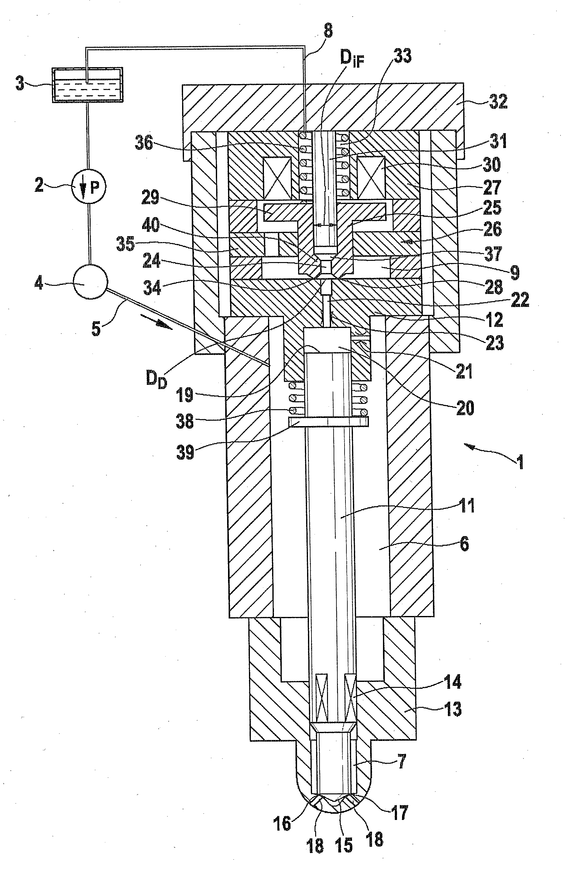
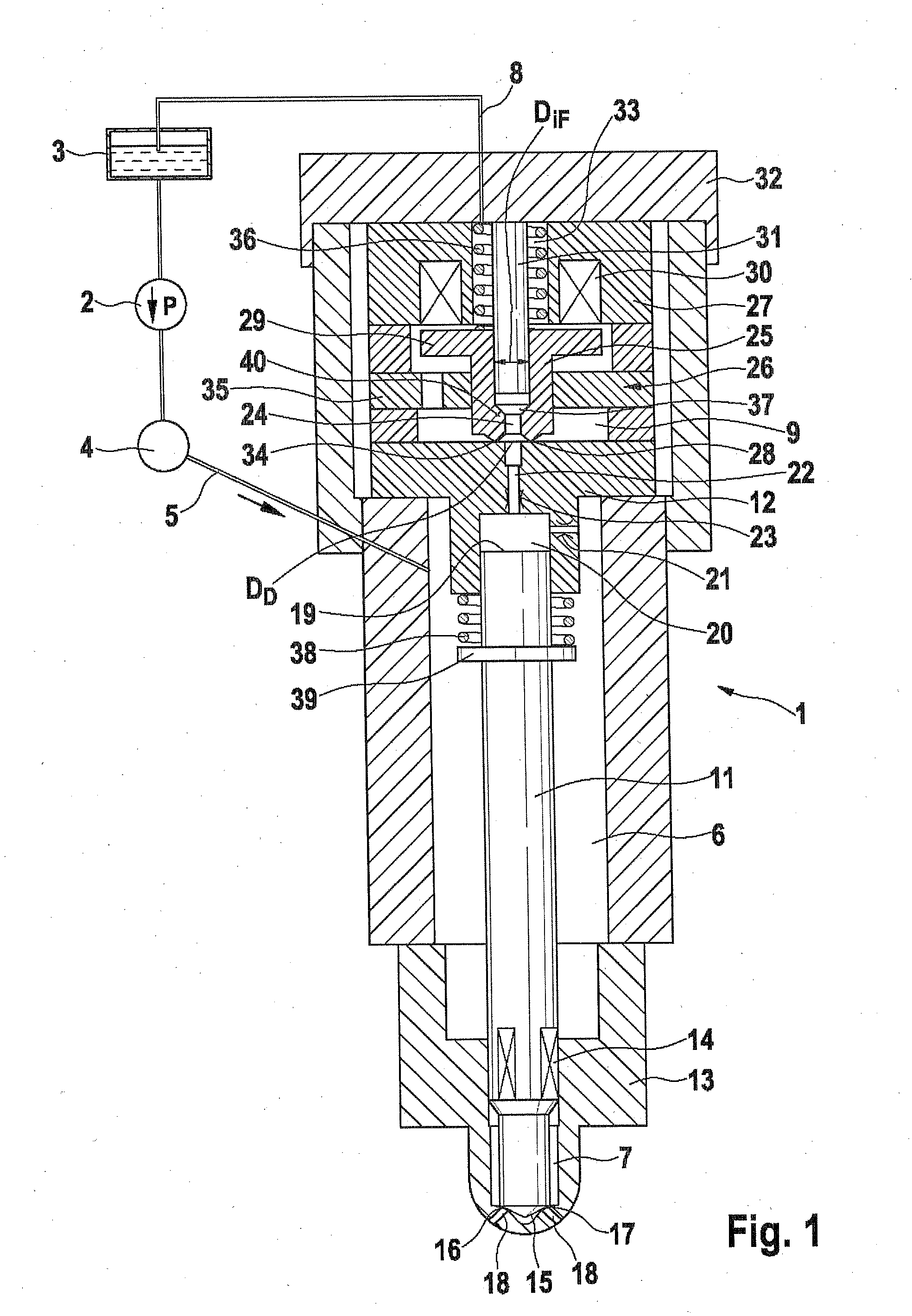
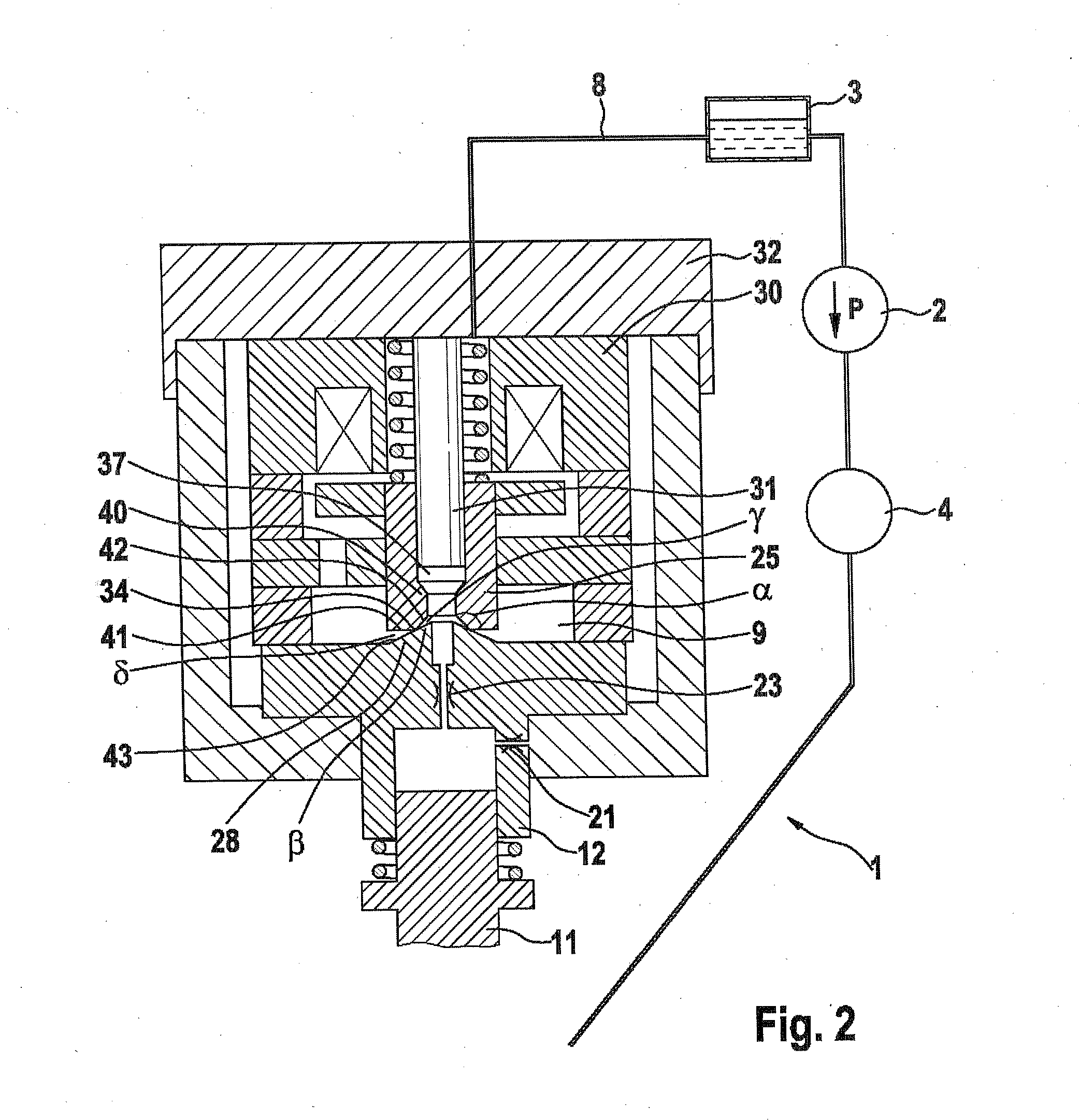
[0019]In the drawings, identical components and components with the same function are identified by the same reference numerals.

[0020]In FIG. 1, an injector 1 embodied as a common rail injector for injecting fuel into a cc, not shown, of an internal combustion engine of a motor vehicle is shown. A high-pressure pump 2 pumps fuel from a tank 3 into a high-pressure fuel reservoir 4 (rail). In it, fuel, in particular diesel or gasoline, is stored at high pressure, which in this exemplary embodiment is approximately 2000 bar. The injector 1 is connected along with other injectors, not shown, to the high-pressure fuel reservoir 4 via a supply line 5. The supply line 5 discharges into a pressure chamber 6. By means of a return line 8, a low-pressure region 9 of the injector 1 is connected to the tank 3. Via the return line 8, a separate control quantity of fuel, to be explained hereinafter, can flow out from the injector 1 to the tank 3.

[0021]An injection valve element 11 is disposed insi...


PUM


Abstract

The invention relates to an injector, in particular, a common-rail injector for injection of fuel into a combustion chamber of an internal combustion engine. An injection valve element, adjustable between a closed position and an open position, is controllable by means of a control valve. The control valve has a control valve element, adjustable between a closed position and an open position by means of an actuator, which in the closed position is an at least almost pressure-equalized and has a sealing line which cooperates in a sealing manner with a control valve seat. The sealing line of the control valve element is lifted off the control valve seat in the open position and hence opens fuel flow from a high pressure region to a low pressure region of the injector. According to the invention, the control valve element has a support region extending over the sealing line in a radial direction to the high pressure region.

Description

PRIOR ART[0001]The invention relates to an injector, in particular a common rail injector, for injecting fuel into a combustion chamber of an internal combustion engine as generically defined by the preamble to claim 1.[0002]From European Patent Disclosure EP 1 612 403 A1, an injector embodied as a common rail injector is known, having an axially pressure-balanced control valve (servo valve) for blocking and opening a fuel outflow conduit from a control chamber. By means of the control valve, the fuel pressure inside the control chamber can be varied, and the control chamber is constantly supplied with fuel at high pressure, via an inflow throttle restriction. By varying the fuel pressure inside the control chamber, an injection valve element is adjusted between an open position and a closed position, and in its open position the injection valve element enables the fuel flow into the combustion chamber of an internal combustion engine. The control valve includes a sleevelike control...

Claims


Application Information

Patent Timeline
Patent Type & Authority Applications(United States)
IPC IPC(8): F02M69/46
CPCF02M47/027F02M63/007F02M2547/003F02M63/0077F02M63/008F02M63/0073
Inventor EISENMENGER, NADJAMAGEL, HANS-CHRISTOPH
Owner ROBERT BOSCH GMBH
Why Eureka
Eureka Blog
Learn More