Fluid Controlled Containment Berm System

a technology of containment berms and fluids, which is applied in the direction of functional valve types, separation processes, filtration separation, etc., can solve the problems of large size, difficult transportation, and inability to compact storage, etc., and achieves the effects of convenient transportation, assembly, disassembly and storage, and low manufacturing cos

Active Publication Date: 2010-11-25
BERG
View PDF24 Cites 7 Cited by
  • Summary
  • Abstract
  • Description
  • Claims
  • Application Information

AI Technical Summary

Benefits of technology

[0021]Another object is to provide a fluid controlled containment berm system that is relatively inexpensive to manufacture compared to conventional containment berms.
[0022]Another object is to provide a fluid controlled containment berm system that is easy to drive onto and out of with a vehicle.
[0023]Another object is to provide a fluid controlled containment berm system that can be easily transported, assembled, disassembled and stored.

Problems solved by technology

A main problem with conventional portable containment berms is that they require significant amounts of time and workers to assemble.
A further problem with conventional portable containment berms is that they are relatively large in size and do not allow for a compact storage size.
Another of the problems with conventional portable containment berms is that the corners of the fabric material are susceptible to tearing when driven over by the vehicle.
While conventional containment berms may be suitable for the particular purpose to which they address, they are not as suitable for automatically forming a containment berm to contain hazardous liquid spills involving a vehicle.
Conventional containment berms typically require extensive setup time to create the supporting walls.

Method used


Image

  • Fluid Controlled Containment Berm System
  • Fluid Controlled Containment Berm System
  • Fluid Controlled Containment Berm System

Examples


Embodiment Construction

A. Overview

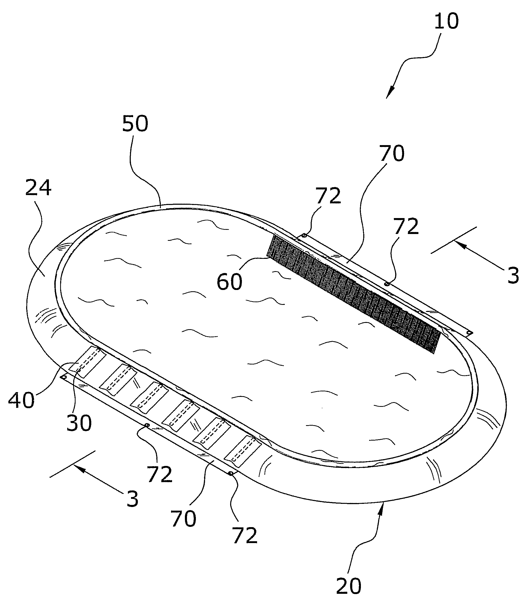
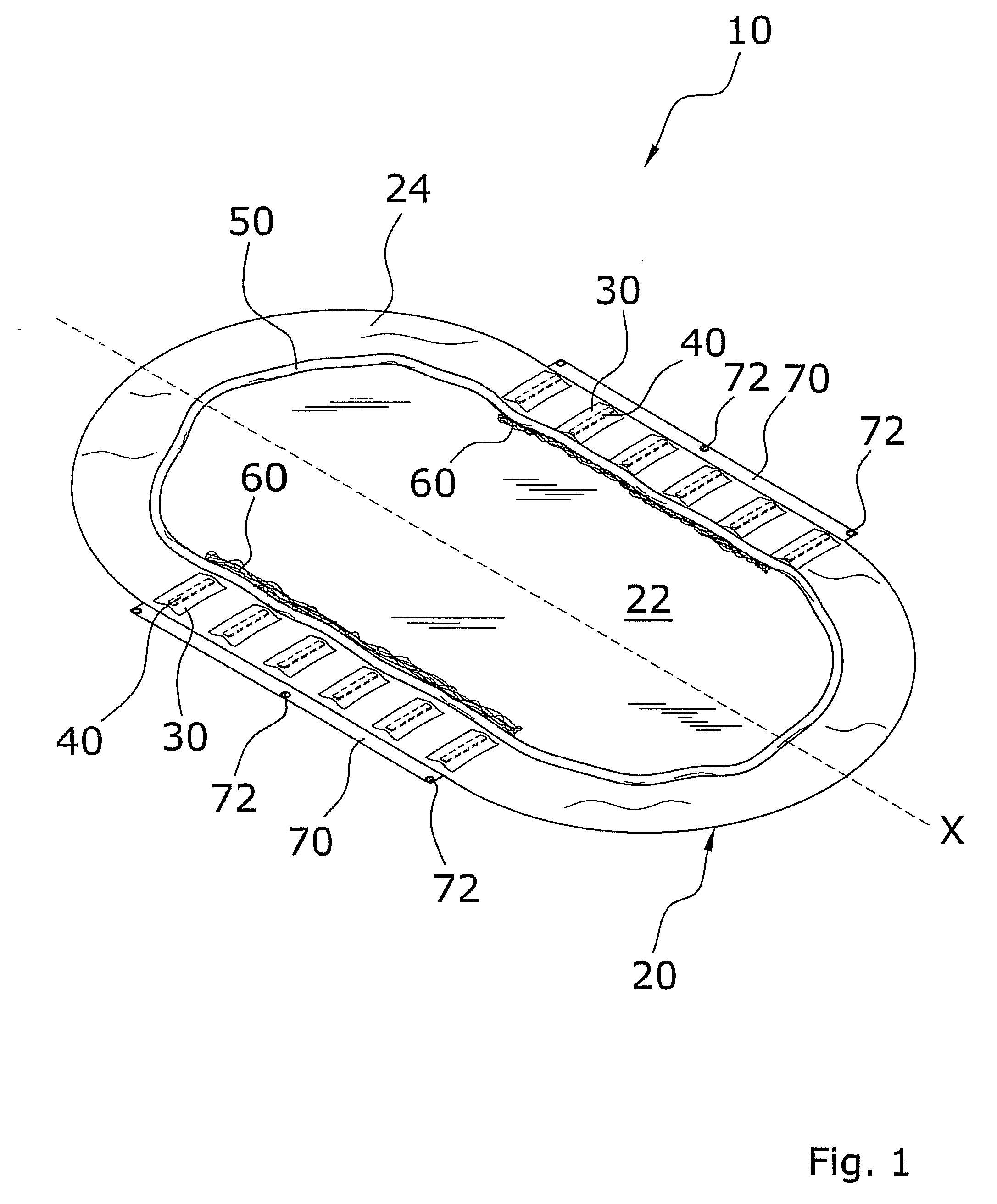
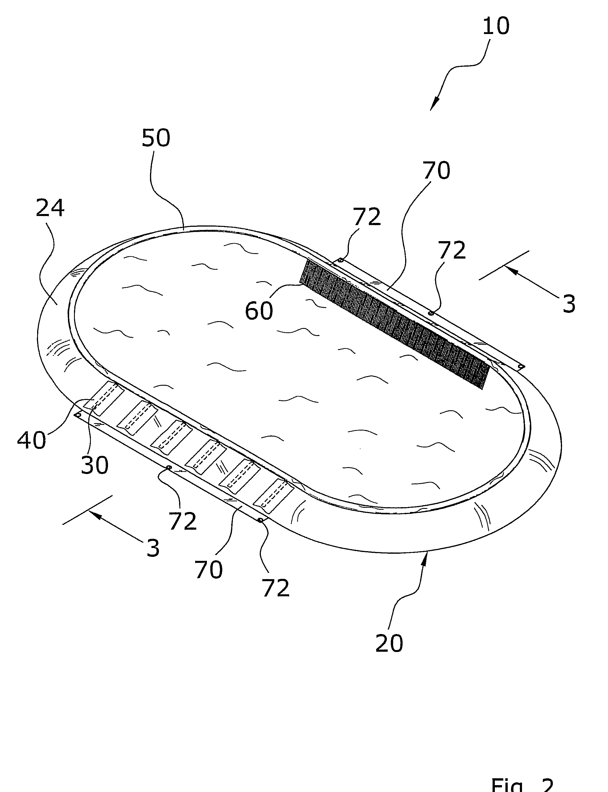
[0039]Turning now descriptively to the drawings, in which similar reference characters denote similar elements throughout the several views, FIGS. 1 through 6b illustrate a fluid controlled contaimnent berm system 10, which comprises a liner 20 including a floor 22 and a sidewall 24, a buoyant member 50 attached to an upper portion of the liner 20, and a pair of diffuser members 60 attached between the floor 22 and the sidewall 24.

B. Liner

[0040]The liner 20 has a floor 22 and at least one sidewall 24 as best illustrated in FIGS. 1 and 2 of the drawings. The liner 20 includes an inner surface and an outer surface, wherein the inner surface is adjacent to the liquid when being filled.

[0041]The liner 20 is preferably comprised of a flexible material to allow the present invention to be folded into a compact storage position as shown in FIGS. 6a and 6b of the drawings. The liner 20 may be comprised of various materials that are commonly utilized within the hazardous material ...


PUM

PropertyMeasurementUnit
diameteraaaaaaaaaa
volumeaaaaaaaaaa
perimeteraaaaaaaaaa

Abstract

A fluid controlled containment berm system for automatically forming a containment berm to contain hazardous liquid spills involving a vehicle. The fluid controlled containment berm system includes a liner including a floor and a sidewall, a buoyant member attached to an upper portion of the liner, and a pair of diffuser members attached between the floor and the sidewall.

Description

CROSS REFERENCE TO RELATED APPLICATIONS[0001]Not applicable to this application.STATEMENT REGARDING FEDERALLY SPONSORED RESEARCH OR DEVELOPMENT[0002]Not applicable to this application.BACKGROUND OF THE INVENTION[0003]1. Field of the Invention[0004]The present invention relates generally to hazardous spill containment berms and more specifically it relates to a fluid controlled containment berm system for automatically forming a containment berm to contain hazardous liquid spills involving a vehicle.[0005]2. Description of the Related Art[0006]Any discussion of the prior art throughout the specification should in no way be considered as an admission that such prior art is widely known or forms part of common general knowledge in the field.[0007]Conventional hazardous material containment berms are typically comprised of a solid concrete pit that the vehicle drives into for loading / unloading of hazardous materials such as chemicals, fuel and the like. Recently, portable hazardous mate...

Claims


Application Information

Patent Timeline
Patent Type & Authority Applications(United States)
IPC IPC(8): B65D1/34
CPCB08B17/025Y10T137/5762
Inventor BARRETT, ANDREW N.DOLSBY, CRAIG G.
Owner BERG
Why Eureka
Try Eureka