Frequency measuring apparatus

a technology of frequency measurement and measuring apparatus, which is applied in the direction of counting chain synchronous pulse counters, pulse techniques, instruments, etc., can solve problems such as inability to determine, and achieve the effect of simplifying the circuit and speeding up the circui

Active Publication Date: 2010-11-25
SEIKO EPSON CORP
View PDF144 Cites 11 Cited by
  • Summary
  • Abstract
  • Description
  • Claims
  • Application Information

AI Technical Summary

Benefits of technology

[0022]By adopting such a configuration, it becomes possible to configure the primary part of the frequency measuring apparatus with a 1-bit circuit, thus the speeding up of the circuit and the simplification of the circuit become easy.
[0023]It is preferable that the short gate time counter section includes a data latch operating at the sampling frequency fs, a 1-bit output binary counter, and a moving average filter with m taps, and the complement determination section performs the determination based on even / odd information of a least significant digit of an integer part of “(2×(approximate value of the frequency) / (sampling frequency fs)×(the number of taps of the moving average filter).” Thus, it becomes possible to configure the frequency measuring apparatus with the circuit in which the binary counter and the moving average filter with m taps are simplified.

Problems solved by technology

Further, in the case of using only the least significant bit of the counter as the short gate time count value, it is not achievable to determine based only on the 1-bit information whether the train of 0 and 1 output from the counter positively corresponds to the magnitude of the count value or they have a complementary relationship.

Method used


Image

  • Frequency measuring apparatus
  • Frequency measuring apparatus
  • Frequency measuring apparatus

Examples


first embodiment

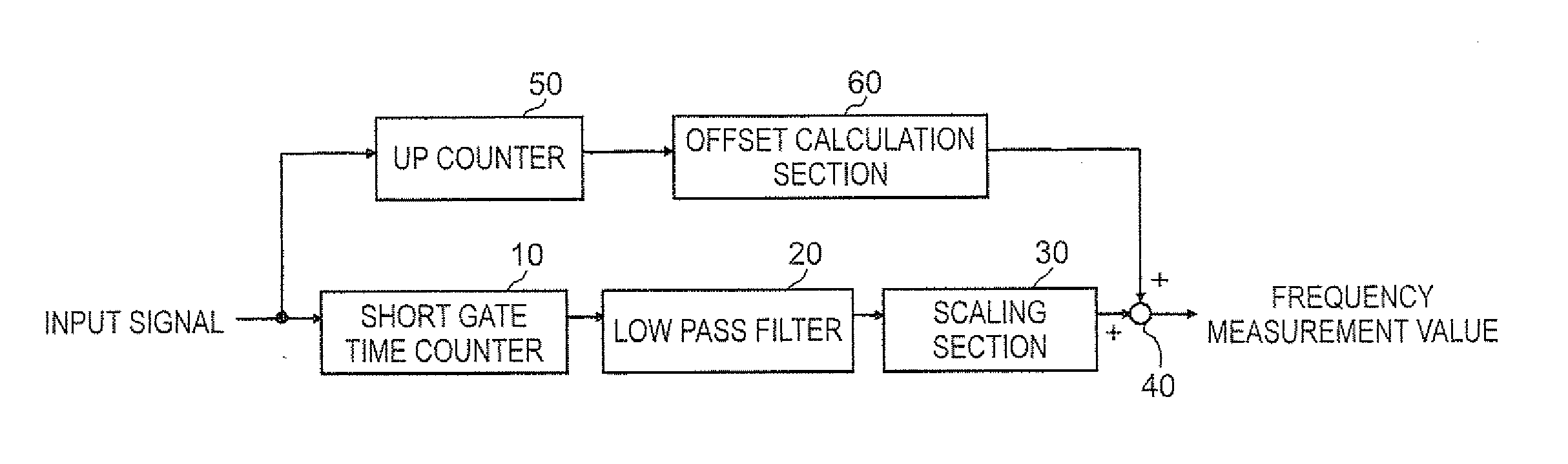
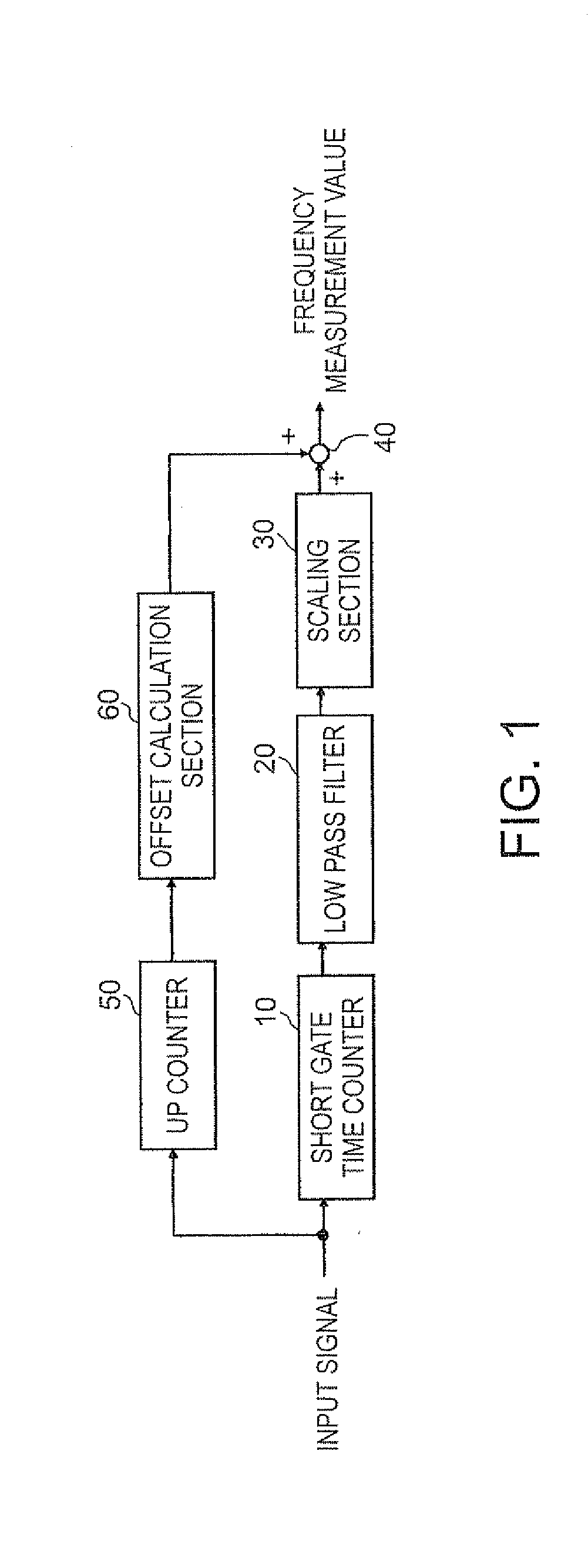
[0044]Embodiments of the invention will hereinafter be described with reference to the accompanying drawings. FIG. 1 shows a first embodiment, wherein the frequency measuring apparatus is composed of, in rough classification, a high-order digit calculation section for obtaining a high-order portion of the frequency of an input signal, a low-order digit calculation section for obtaining lower digits of the frequency with good accuracy using the short gate time count method, and an adding section for combining the outputs of the respective calculation sections.

[0045]The low-order digit calculation section is mainly composed of a short gate time counter section 10, a low pass filter section 20, and a scaling section 30. The high-order digit calculation section is mainly composed of an up counter section 50 and an offset calculation section 60. The adding section is constituted with an adder 40.

[0046]Although not limited thereto, the input signal to be the object of the frequency measur...

second embodiment

[0060]FIGS. 4 through 8 are diagrams for explaining an example of adopting a simple configuration as the configuration of the short gate time counter section 10 in the case in which the input signal is a binary signal. In each of the drawings, sections corresponding to those shown in FIG. 1 are denoted with the same reference numerals, and the description therefor will be omitted.

[0061]FIG. 4 shows an example of configuring the short gate time counter section 10 of the frequency measuring apparatus shown in FIG. 1 with a 1-bit output (binary output) binary counter. In the case in which the sampling is performed by the 1-bit output binary counter to output the count value, as described later, there are two cases, one is the case in which the output value train positively corresponds to the magnitude of the count value, and the other is the case in which the output value train is reversed (complement) thereto.

[0062]Therefore, in the present embodiment, there are provided a quotient ca...


PUM


Abstract

A frequency measuring apparatus includes: a high-order digit calculation section adapted to measure an input signal and output a high-order digit value of a frequency value of the input signal; a low-order digit calculation section adapted to measure the input signal and output a low-order digit value of the frequency value of the input signal; and an adding section adapted to add the high-order digit value and the low-order digit value to each other to output the frequency value of the input signal.

Description

[0001]The entire disclosure of Japanese Patent Application No. 2009-123779, filed May 22, 2009 is expressly incorporated by reference herein.BACKGROUND[0002]1. Technical Field[0003]The present invention relates to a frequency measuring apparatus or the like, and in particular to improvement and so on of a frequency measuring apparatus for making it possible to measure an absolute frequency using a frequency measuring apparatus of a short gate time count method for counting an input signal in a predetermined time period, and removing a high-frequency component from a counted value train, thereby detecting a frequency variation component.[0004]2. Related Art[0005]As a method of measuring a frequency, there are known a direct count method (see, e.g., JP-A-2001-119291) of counting pulses passing therethrough in a predetermined gate time, a reciprocal method (see, e.g., JP-A-5-172861) of accurately measuring the pulse period and obtaining the frequency using the inverse of the period thu...

Claims


Application Information

Patent Timeline
Patent Type & Authority Applications(United States)
IPC IPC(8): G01R23/02
CPCG01R23/02
Inventor TODOROKIHARA, MASAYOSHI
Owner SEIKO EPSON CORP
Why Eureka
Try Eureka