Fuel cell

a fuel cell and metal clip technology, applied in the field of fuel cells, can solve the problems of inefficiency of assembling operation, laborious operation of attaching metal clip members, and inability to efficiently carry so as to achieve the effect of efficiently carrying out assembling operation of fuel cells

Active Publication Date: 2010-11-25
HONDA MOTOR CO LTD
View PDF5 Cites 14 Cited by
  • Summary
  • Abstract
  • Description
  • Claims
  • Application Information

AI Technical Summary

Benefits of technology

[0010]The present invention has been made to solve the problems of this type, and an object of the present invention is to provide a fuel cell which makes it possible to assemble a plurality of the fuel cells easily and rapidly and carry out the assembling operation of the fuel cell efficiently, and to provide a method of producing such a fuel cell.

Problems solved by technology

Therefore, the operation of attaching the metal clip members is laborious.
In particular, at the time of assembling the fuel cell stack by stacking several hundreds of fuel cells, considerable time and labor are required for the operation.
Therefore, the assembling operation cannot be performed efficiently.
At this time, metal clip members need to be detached, and this detaching operation is considerably laborious.

Method used


Image

  • Fuel cell
  • Fuel cell
  • Fuel cell

Examples


first embodiment

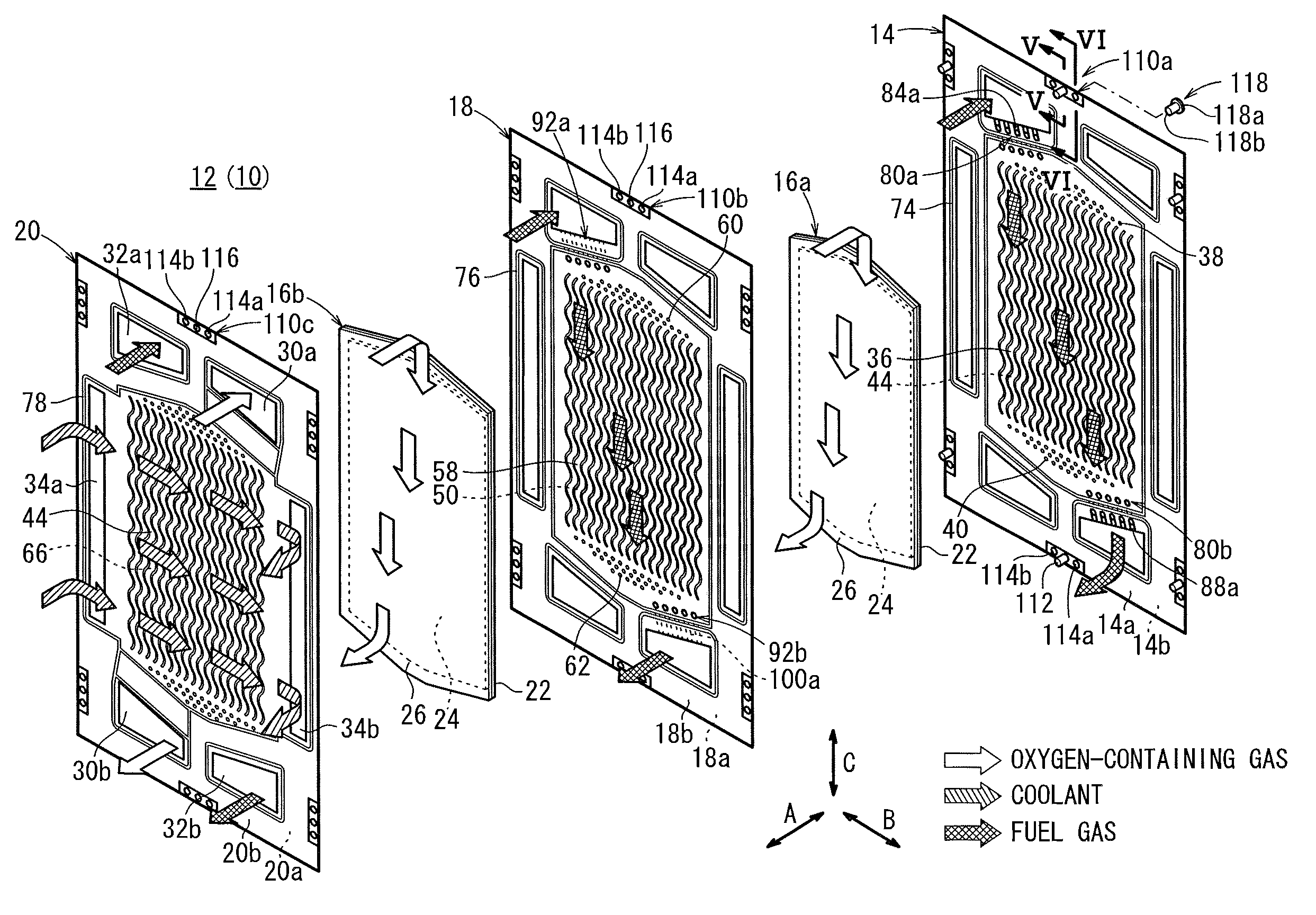
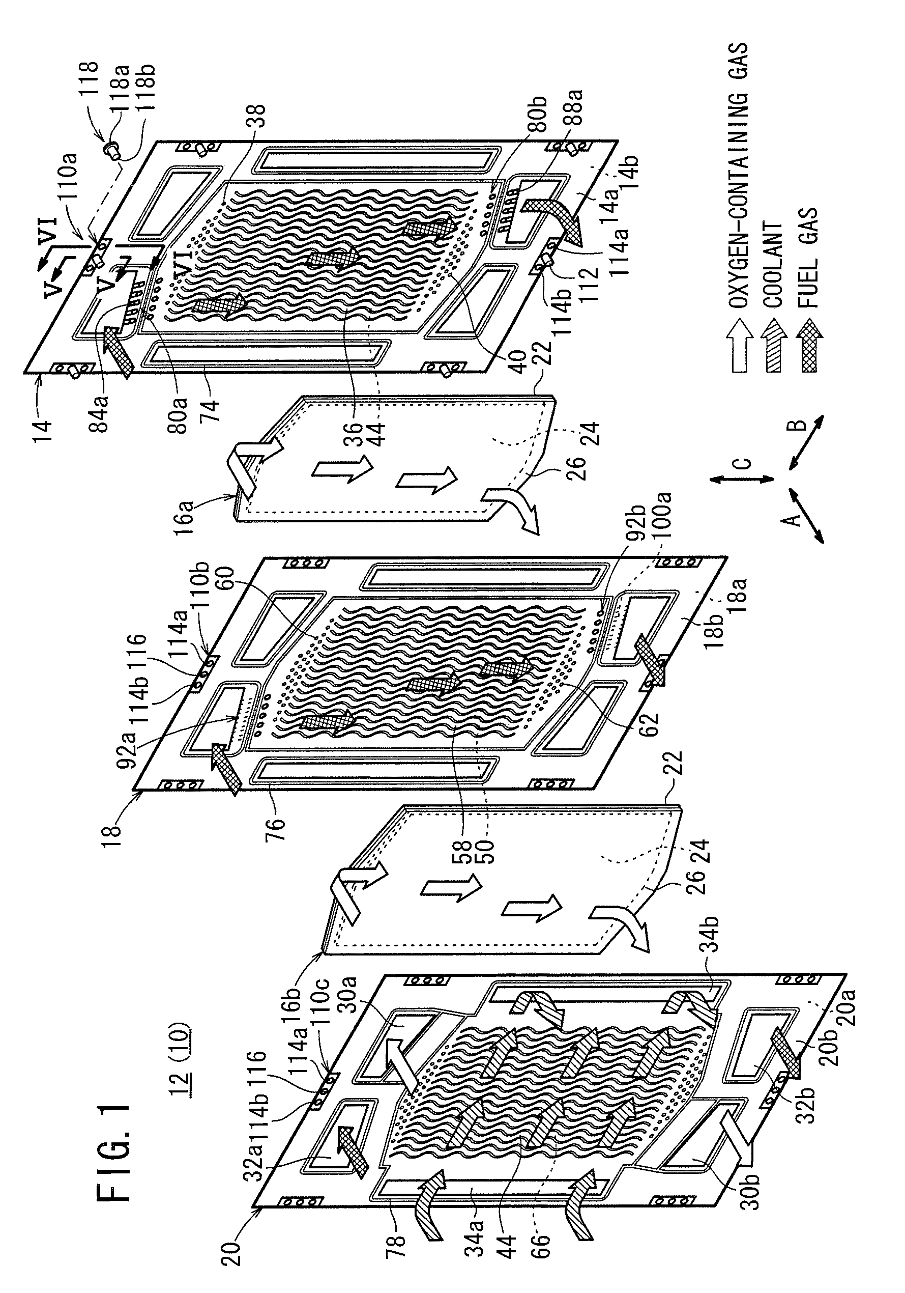
[0044]As shown in FIG. 1, the fuel cell 10 according to the present invention is formed by stacking a plurality of cell units 12 in a horizontal direction indicated by an arrow A or in a gravity direction indicated by an arrow C. Each of the cell units 12 includes a first separator 14, a first membrane electrode assembly (electrolyte electrode assembly) (MEA) 16a, a second separator 18, a second membrane electrode assembly 16b, and a third separator 20.

[0045]For example, the first separator 14, the second separator 18, and the third separator 20 are metal separators of steel plates, stainless steel plates, aluminum plates, plated steel sheets, or metal plates having anti-corrosive surfaces by surface treatment. Each of the first separator 14, the second separator 18, and the third separator 20 is formed by corrugating a metal thin plate under pressure, and has a corrugated shape in cross section. Instead of using the metal separators, carbon separators may be used as the first separ...

second embodiment

[0101]FIG. 8 is a cross sectional view showing main components of a cell unit 132 of a fuel cell 130 according to the present invention.

[0102]The constituent elements that are identical to those of the fuel cell 10 according to the first embodiment are labeled with the same reference numerals, and description thereof will be omitted. Likewise, in third and other embodiments described later, the constituent elements that are identical to those of the fuel cell 10 according to the first embodiment are labeled with the same reference numerals, and description thereof will be omitted.

[0103]A cell unit 132 includes the first separator 14, the second separator 18, and the third separator 20, and resin connecting sections 134a, 134b, and 134c are provided in the outer circumferential ends of the first separator 14, the second separator 18, and the third separator 20, respectively. A coupling pin 136 projecting in the stacking direction is molded integrally with each resin connecting sectio...

third embodiment

[0106]FIG. 9 is an exploded perspective view showing main components of a fuel cell 140 according to the present invention.

[0107]The fuel cell 140 is formed by stacking a plurality of cell units 142. Each of the cell units 142 includes a first separator 144, a membrane electrode assembly 146, and a second separator 148.

[0108]At an upper end of the cell unit 142 in a longitudinal direction indicated by an arrow C, an oxygen-containing gas supply passage 30a, a fuel gas supply passage 32a, and a coolant supply passage 34a are formed. At a lower end of the cell unit 142 in the longitudinal direction, an oxygen-containing gas discharge passage 30b, a fuel gas discharge passage 32b, and a coolant discharge passage 34b are formed.

[0109]The first separator 144 has a fuel gas flow field 36A on its surface 14a facing the membrane electrode assembly 146, and the second separator 148 has an oxygen-containing gas flow field 50A on its surface 20a facing the membrane electrode assembly 146. A co...


PUM

PropertyMeasurementUnit
temperatureaaaaaaaaaa
diameteraaaaaaaaaa
circumferencesaaaaaaaaaa

Abstract

A cell unit of a fuel cell includes a first separator, a first membrane electrode assembly, a second separator, a second membrane electrode assembly, and a third separator. Resin connecting sections are provided in the outer circumferential ends of the first separator, the second separator, and the third separator. A coupling pin is molded integrally with the resin connecting section of the first separator. A first hole and a second hole are formed on both sides of the coupling pin for selectively inserting a rebuilt pin into either of the first and second holes. A hole for inserting the coupling pin is formed at the center, and the first hole and the second hole are formed on both sides of the hole, in each of the resin connecting sections of the second and third separators.

Description

CROSS-REFERENCE TO RELATED APPLICATION[0001]This application is based upon and claims the benefit of priority from Japanese Patent Applications No. 2009-122401 filed on May 20, 2009 and No. 2009-122403 filed on May 20, 2009, of which the contents are incorporated herein by reference.BACKGROUND OF THE INVENTION[0002]1. Field of the Invention[0003]The present invention relates to a fuel cell formed by stacking a membrane electrode assembly and separators. The membrane electrode assembly includes a pair of electrodes, and an electrolyte membrane interposed between the electrodes. Further, the present invention relates a method of producing the fuel cell.[0004]2. Description of the Related Art[0005]For example, a solid polymer electrolyte fuel cell employs a membrane electrode assembly (MEA) which includes an anode, a cathode, and an electrolyte membrane interposed between the anode and the cathode. The electrolyte membrane is a polymer ion exchange membrane. The membrane electrode asse...

Claims


Application Information

Patent Timeline
Patent Type & Authority Applications(United States)
IPC IPC(8): H01M8/10H01M8/00
CPCH01M8/0276H01M8/0297Y02E60/50H01M2008/1095H01M8/247H01M8/026H01M8/241H01M8/2483H01M8/0267
Inventor FUKUTA, MASAHIROISHIDA, KENTAROSHISHIDO, TATSURU
Owner HONDA MOTOR CO LTD
Why Eureka
Try Eureka