
Collision avoidance and warning system

a technology applied in the field of collision avoidance and warning system, can solve the problems of stinger providing minimal protection, presenting an extremely dangerous hazard to nearby personnel, and affecting the safety of personnel,

Active Publication Date: 2010-11-25
TEXTRON INNOVATIONS
View PDF43 Cites 36 Cited by
  • Summary
  • Abstract
  • Description
  • Claims
  • Application Information

AI Technical Summary

Problems solved by technology

On many such helicopters, the tail rotor is positioned close enough to the ground that it presents an extremely dangerous hazard to nearby personnel while the helicopter engine is running (and the rotor is turning).
Also, during low-level flight, there is a risk of a tail rotor strike with the ground, ground structures, vegetation, or personnel, due in part to the difficulty or inability of a pilot to see the tail rotor and the immediate area around the tail rotor.
This method is disadvantageous due to the fact that an actual impact will still occur and this method is limited to preventing only certain types of impacts.
For example, a tail stinger will only transfer energy if the stinger is impacted first; the tail stinger provides minimal protection for an impact from the side or above.
However, there is still a disadvantage to this method since a person may still come into contact with the guard before their movement into the danger zone is impeded.
Also, not all angles of approach are impeded by most mechanical guards.
Outfitting tail rotors with high-visibility paint schemes has resulted in a decrease in the number of accidents due to persons walking into an operating tail rotor; however, this method is not effective in low-light or dark conditions or for preventing the helicopter from flying into obstacles.
However, this method disadvantageously relies on optics that are prone to degraded performance in dust or other environments where the optical lenses of the system can be obscured by particulate matter in the air.
The device shown is also mounted on the underside of the aircraft, limiting its field of view and can be greatly obscured by dust or other vegetation as part of an unprepared landing site.
Laser energy can also see higher reflectivity due to a high density of particulate, making it prone to errors, false alarms, or non-alert due to blinding.

Method used


Image

  • Collision avoidance and warning system
  • Collision avoidance and warning system
  • Collision avoidance and warning system

Examples


Embodiment Construction

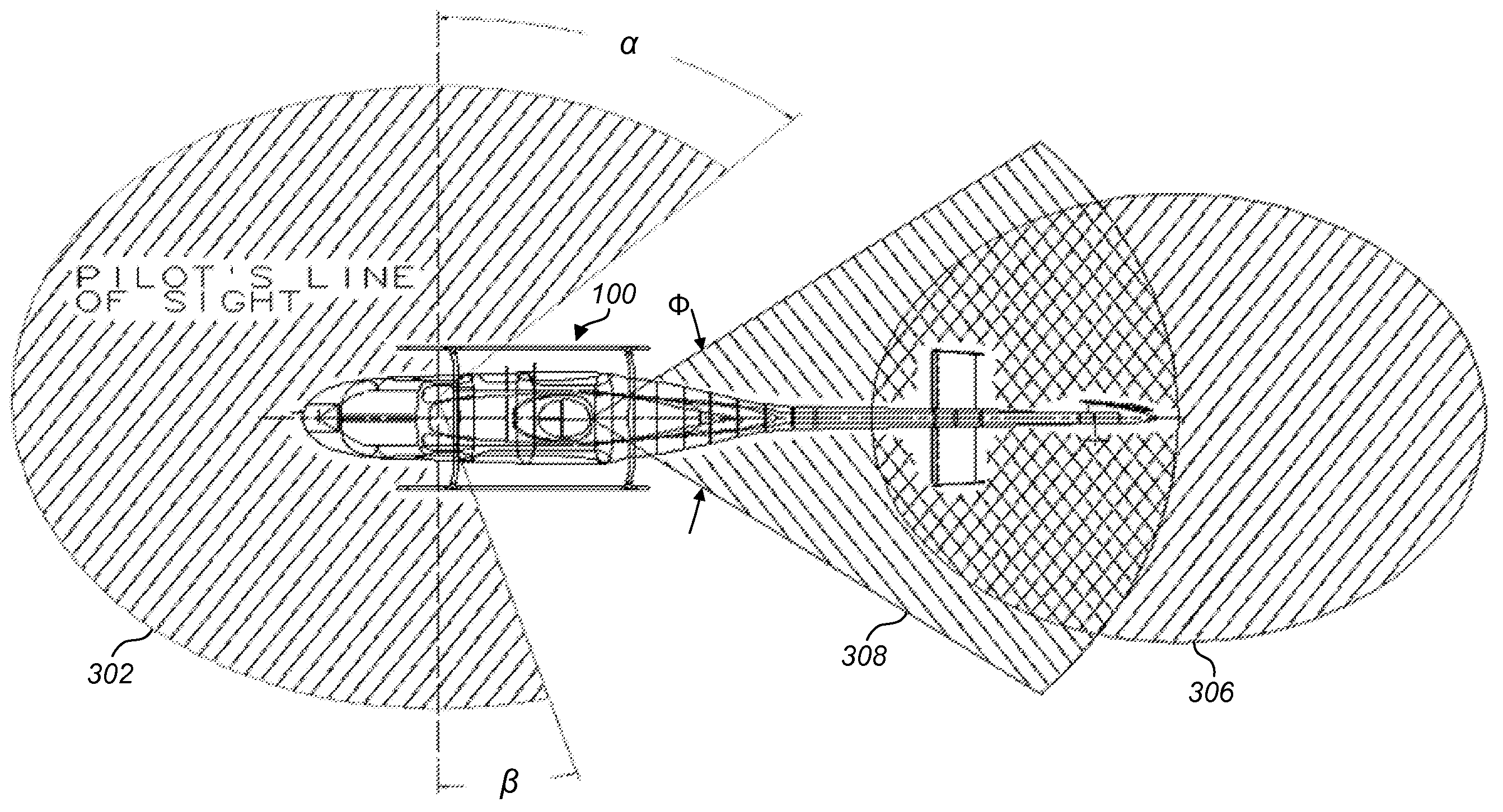
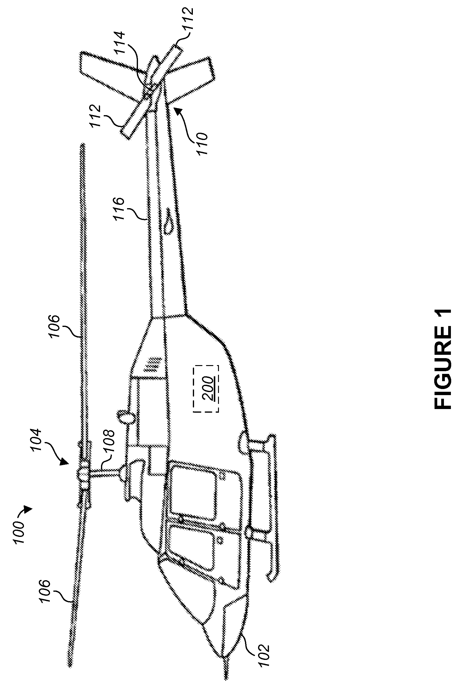
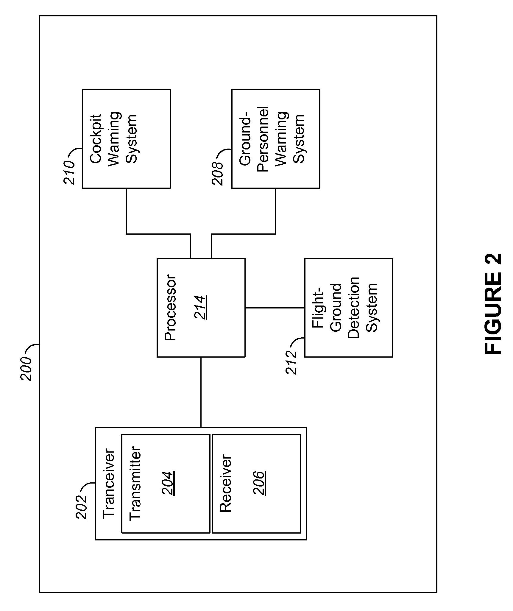
[0014]Referring to FIG. 1 in the drawings, a helicopter 100 having a collision avoidance and warning system, generally designated as system 200, according to the present disclosure is illustrated. It will be appreciated that system 200 can include multiple sub-elements that are dispersed within the helicopter 100 rather than all located in a single location. Helicopter 100 has a fuselage 102 and a main rotor assembly 104, including main rotor blades 106 and a main rotor shaft 108. Helicopter 100 has a tail rotor assembly 110, which serves as an example of an anti-torque system. The tail rotor assembly 110 includes tail rotor blades 112 and a tail rotor shaft 114. Main rotor blades 106 generally rotate about a longitudinal axis of main rotor shaft 108. Tail rotor blades 112 generally rotate about a longitudinal axis of tail rotor shaft 114. Main rotor blades 106 and tail rotor blades 112 are driven by a drive means (not shown) carried by fuselage 102. Torque is transmitted from the d...


PUM


Abstract

A collision avoidance and warning system for a helicopter uses a type of emitted energy, for example radio frequency radar, from a transceiver positioned to cover a selected field of view for detecting an object or pedestrian in the vicinity of the helicopter. For helicopters that include a tail rotor assembly, the selected field of view can include a region around the tail rotor assembly so that when the helicopter is running on the ground, an alarm can be issued to persons approaching the tail rotor assembly. When the helicopter is in flight, the collision avoidance and warning system can alert the pilot when a portion of the helicopter outside of the pilot's field of view is in danger of a collision with an object.

Description

BACKGROUND[0001]1. Field of the Invention[0002]The present application relates to systems for detecting a probable collision and issuing an alert regarding the probable collision.[0003]2. Description of Related Art[0004]Many helicopters use a tail rotor anti-torque system. On many such helicopters, the tail rotor is positioned close enough to the ground that it presents an extremely dangerous hazard to nearby personnel while the helicopter engine is running (and the rotor is turning). Also, during low-level flight, there is a risk of a tail rotor strike with the ground, ground structures, vegetation, or personnel, due in part to the difficulty or inability of a pilot to see the tail rotor and the immediate area around the tail rotor.[0005]Because of these known problems, various efforts have been made to reduce the risk of injury and damage caused by tail rotor strikes. However, it is also important to take steps towards reducing impacts with other portions of an aircraft, particula...

Claims


Application Information

Patent Timeline
IPC IPC(8): G08G5/04G01S13/933
CPCG08G5/04G01S13/933G08G5/0021G08G5/0052G08G5/0078G08G5/0086G08G5/045G08G5/065
Inventor MCCOLLOUGH, JAMESBAIS, CHRISTOS
Owner TEXTRON INNOVATIONS
Learn More