End-to-End Design of Electro-Optic Imaging Systems Using the Nonequidistant Discrete Fourier Transform

Inactive Publication Date: 2010-11-25
RICOH KK
View PDF45 Cites 9 Cited by
  • Summary
  • Abstract
  • Description
  • Claims
  • Application Information

AI Technical Summary

Benefits of technology

[0009]The present invention overcomes the limitations of the prior art by accelerating the end-to-end design of electro-optic imaging systems, for example by allowing more flexibility in the choice of sampling grids which can then be better suited to

Problems solved by technology

First, the optical subsystem is designed with the goal of forming a high quality intermediate optical image of the source (subject to cost, physical and other non-imaging constraints).
One drawback to the traditional design approach is that synergies between the optical subsystem and the digital image processing subsystem may be o

Method used


Image

  • End-to-End Design of Electro-Optic Imaging Systems Using the Nonequidistant Discrete Fourier Transform
  • End-to-End Design of Electro-Optic Imaging Systems Using the Nonequidistant Discrete Fourier Transform
  • End-to-End Design of Electro-Optic Imaging Systems Using the Nonequidistant Discrete Fourier Transform

Examples


Embodiment Construction

Introduction

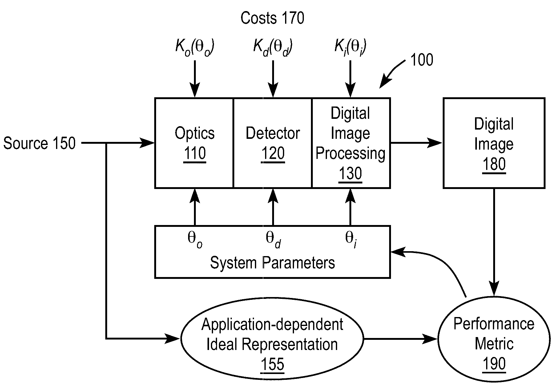
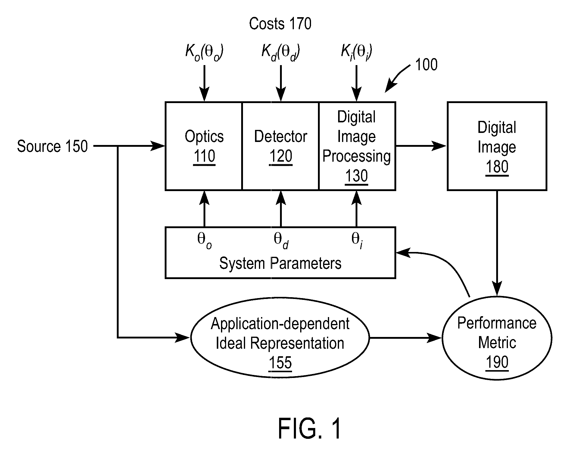
[0026]FIG. 1 is a block diagram illustrating the problem of designing an electro-optic imaging system 100. The imaging system 100 includes an optical subsystem 110, detector subsystem 120 and digital image processing subsystem 130. The imaging system 100 is intended to image a source 150 and produces digital image 180. The general design problem is to design the imaging system 100 to “optimize” its overall performance, subject to certain constraints. In many cases, the goal of optimization is to produce a digital image 180 which matches the application-specific idealized version 155 of the input source.

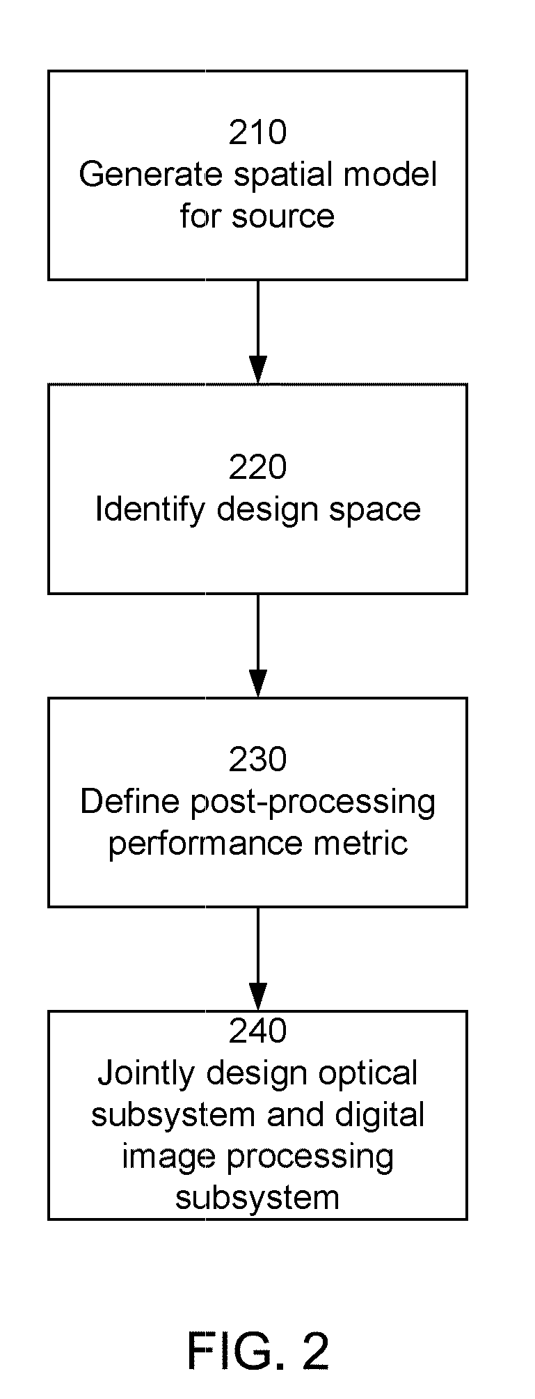
[0027]FIGS. 1 and 2 illustrate an example method for designing an electro-optic imaging system 100 according to the present invention. Referring to FIG. 2, the design method includes generating 210 a spatial model of the source 150. The spatial model of the source may be derived for a specific situation, empirically measured, based on previously developed models or otherwi...


PUM


Abstract

A unified design strategy takes into account different subsystems within an overall electro-optic imaging system. In one implementation, the design methodology predicts end-to-end imaging performance using a spatial model for the source and models for the optical subsystem, the detector subsystem and the digital image processing subsystem. The optical subsystem and digital image processing subsystems are jointly designed taking into account the entire system. Unconventional techniques such as the nonequidistant DFT (nDFT) are used to accelerate the design process.

Description

BACKGROUND OF THE INVENTION[0001]1. Field of the Invention[0002]This invention relates generally to the design of electro-optic imaging systems, and more particularly, to the “end-to-end” design of these systems using nonequidistant discrete Fourier transforms, including for example the nonequidistant fast Fourier transform.[0003]2. Description of the Related Art[0004]Electro-optic imaging systems typically include an optical subsystem (e.g., a lens assembly), an electronic detector subsystem (e.g., CCD detector array) and a digital image processing subsystem (e.g., typically implemented in dedicated chips or software). Traditional methods for designing these systems generally involve two discrete stages. First, the optical subsystem is designed with the goal of forming a high quality intermediate optical image of the source (subject to cost, physical and other non-imaging constraints). Next, after the optical subsystem has been designed, the digital image processing subsystem is de...

Claims


Application Information

Patent Timeline
IPC IPC(8): G06F17/10G06F17/50
CPCG06F2217/08G06F17/5009G06F30/20G06F2111/06
Inventor ROBINSON, M. DIRKBERKNER, KATHRIN
Owner RICOH KK
Why Eureka
Try Eureka