Radiation heat collection device

a technology of radiation heat collection and heat collection tube, which is applied in the direction of solar heat collectors with working fluids, solar radiation concentration, solar heat collectors safety, etc., can solve the problems of high cost of absorber tubes, significant yield loss, and loss of vacuum, and achieve the effect of reducing the level of inoperativity

Inactive Publication Date: 2010-12-02
ARIES ING Y SISTEMAS
View PDF5 Cites 28 Cited by
  • Summary
  • Abstract
  • Description
  • Claims
  • Application Information

AI Technical Summary

Benefits of technology

[0020]One object of this invention is to provide robust, controllable thermoelectric plants that ensure a minimum level of inoperativity, caused by the breaking of their components and the need for complex maintenance operations to replace them, during their operating life.

Problems solved by technology

The disadvantages of the solar collection devices known in the state of the art include the following:High cost of the absorber tubes.Breaking of the glass-metal joints, with the consequent loss of vacuum and, therefore, of yield.Breaking of the glass tube at the joint areas.Need to perform costly temperature and vacuum degasification processes that allow to activate the getter system.Undetectability of the loss of vacuum in a tube or great uncertainty of the tracers specified, with low confidence regarding the information prior to the failure.Possible saturation of H2 in the getter system through time for temperatures below the working temperature, which would cause a significant loss of yield.Impossibility to easily measure the vacuum during the device's operating life.Need to use materials such as glass for the envelope tube and glass-metal joints due to the high level of vacuum required.High replacement cost in the event of breakage.Impossibility to repair the replaced element.Limited useful surface due to the need to absorb the differential dilations between the inner tube and the outer cover by means of bellows and connecting elements.

Method used


Image

  • Radiation heat collection device
  • Radiation heat collection device
  • Radiation heat collection device

Examples


first embodiment

[0072]As regards the segment joints of outer envelope tube 33, below we will describe this invention, in accordance with FIGS. 8-10.

[0073]Each joint 51 comprises:[0074]Two flanges 53, 53′ with axial tightening means (FIGS. 8 and 9 do not show the typical bolts used in this type of flanges, but they do show the flange openings), the configuration whereof includes sloping surfaces 55, 55′, which co-operate with enlarged edges 57, 57′ of the ends of segments 35, 35′ of envelope tube 33 through contact elements 59, 59′; these have a high elasticity and a low hardness in order to prevent the generation of local stresses in the glass.[0075]A ring 61, placed between flanges 53, 53′, with two hermetic sealing bands 63, 63′ designed to maintain the vacuum, with a fixation base 69 on a support 23.[0076]An insulation crown 62 bound to ring 61, and support and slide means for inner absorber tube 31, consisting of inner radial teeth 64 which provide point contacts with inner absorber tube 31 and...

second embodiment

[0081]In a second embodiment, as may be observed in FIGS. 11-14, joints 81 comprise:[0082]Two clamp-flanges 83, 83′ with radial tightening means (not shown) that join to frames 84, 84′, which are fixed on supports 23.[0083]An insulation crown 85 with, on the one hand, slots 87, 87′ designed to receive the pair of segments 35, 35′ of outer envelope tube 33, with sufficient clearance to this end, and, on the other hand, support and slide means for inner absorber tube 31 consisting of inner radial teeth 86 which provide point contacts for inner absorber tube 31 and allow it to slide with a suitable tribologic behaviour that minimizes friction and wear. Insulation crown 85 also fulfils a thermal insulation function in order to minimize losses by conduction. Preferably, it is made of a ceramic material.[0084]Two pairs of sealing bands 89, 89′ placed on lateral openings of insulation crown 85, on the edges of said slots 87, 87′, such that said segments 35, 35′ remain between them and, con...

third embodiment

[0087]In the invention, illustrated in FIGS. 15-18, a group of two segments 36, 37 of outer envelope tube 33 is united by means of a joint 95 fixed onto a support 23 and the ends of that group are united to other adjacent groups by means of pairs of joints 95′ supported in a displaceable manner on a support 23 with an intermediate bellows device 97 which, in turn, facilitates welding of the components of inner absorber tube 31 between two joints 95′ by the contraction of bellows 97 and the subsequent assembly thereof.

[0088]As observed in FIG. 15, the group formed by segments 36 and 37, which has a length L of, for example, 12 m, is centrally united by a joint 95 fixed onto a support 23 and, on the ends, by joints 95′ supported in a displaceable manner on supports 23. In turn, end joints 95′ of each group are connected by means of a bellows 97. The arrows, f, indicate the displacements of the end joints as a consequence of the dilations of segments 36, 37 of outer envelope tube 33.

[0...


PUM


Abstract

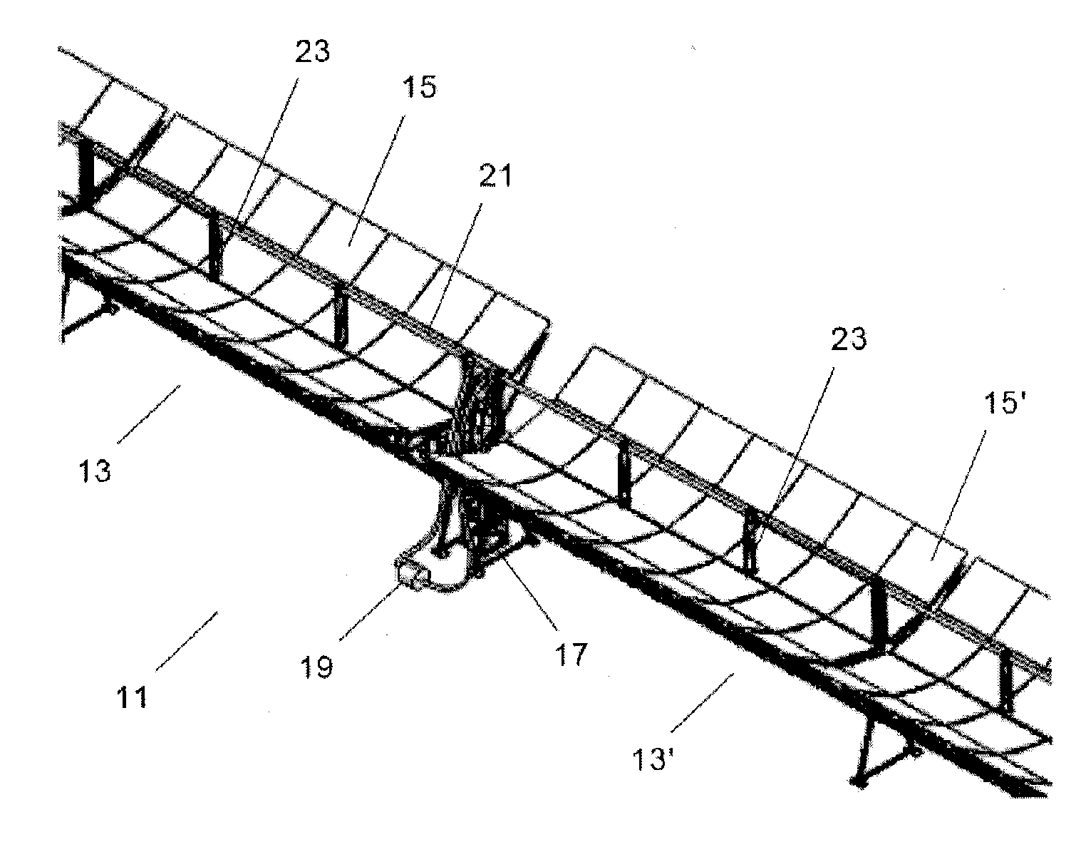
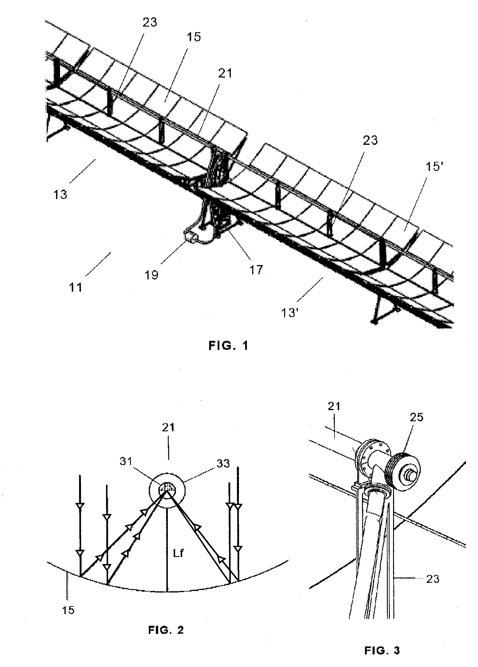
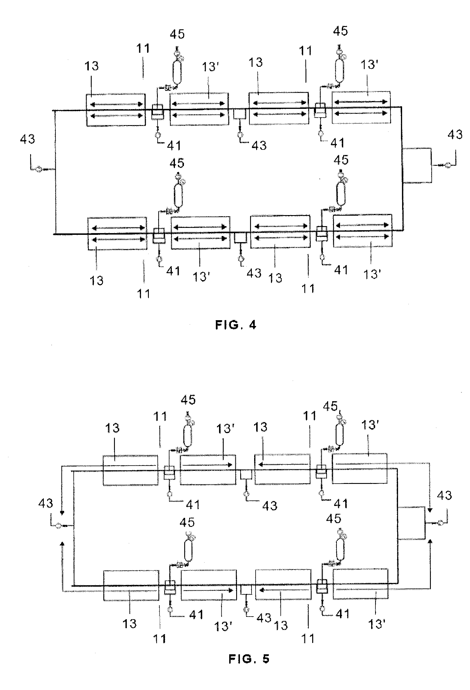
This invention relates to a device that comprises at least one collection unit (11), equipped with a collection tube (21) placed on supports (23), which is formed by an inner absorber tube (31) shaped as a continuous tube and an outer envelope tube (33). The collection unit (11) also comprises reflectors (15) that direct the radiation toward the collection tube (21). Moreover, the device comprises means (41, 43) designed to maintain the collection tube (21) space between the absorber tube (31) and the envelope tube (33) at a pressure of between 5·10−1-5·10−2 mbar. The main advantages of the invention include the reduction in the breaking of glass due to the lower stresses to fatigue, an increase in the effective collection surface (97%-98%) and active management of the vacuum, which makes it possible to monitor the evolution thereof at all times.

Description

FIELD OF THE INVENTION[0001]This invention relates to a radiation heat collection device and, more particularly, to a heat collection device which uses a parabolic reflector that focuses the solar heat radiation onto an absorber tube.BACKGROUND OF THE INVENTION[0002]The solar heat collection devices that use cylindrical-parabolic concentrators known in the state of the art are based on the developments arising from the construction of thermoelectric plants called “Segs”, which were implemented in the United States in the 1980s.[0003]The known designs use structures that act as supports for the reflector elements that make up the parabolic reflector profile and the absorber tube located on the theoretical focal line of the parabolic cylinder formed by the reflectors. These structures are usually formed by inter-connected modules and equipped with an orientation mechanism that makes it possible to collect the maximum possible radiation by following the sun.[0004]The reflector elements...

Claims


Application Information

Patent Timeline
Patent Type & Authority Applications(United States)
IPC IPC(8): F24J2/14F24J2/50F24J2/24F24S10/40F24S10/70F24S23/74
CPCF24J2/055F24J2/14F24J2/4636Y02E10/44Y02E10/45F24J2/4647F24S10/45F24S23/74F24S40/80F24S80/30Y02E10/40
Inventor CARRASCOSA PEREZ, MARCO ANTONIOLUNA SANCHEZ, MANUEL JULIANGARCIA-MIJAN GOMEZ, ABELRUEDA JIMENEZ, FERNANDO
Owner ARIES ING Y SISTEMAS
Why Eureka
Try Eureka