High pressure discharge lamp

a discharge lamp and high-pressure technology, applied in the manufacture of electric discharge tubes/lamps, cold cathode manufacture, electrode systems, etc., can solve problems such as unsatisfactory resolution, and achieve the effect of reducing viscosity and increasing mobility

Inactive Publication Date: 2010-12-02
OSRAM GMBH
View PDF9 Cites 1 Cited by
  • Summary
  • Abstract
  • Description
  • Claims
  • Application Information

AI Technical Summary

Benefits of technology

[0027]Owing to the holding temperature, which is higher than the soldering temperature, this solder has a lower viscosity than conventional solders. The solder can therefore enter very fine pores owing to capillary forces, and permanently seal them successfully.
[0028]The extended holding time, at temperatures which are higher than the soldering temperature, leads to crystallization of the solder, predominantly with Al2O3 being crystallized out. The crystallization of Al2O3 takes place by depletion of Dy2O3 in the melt. The reason is that owing to its higher mobility, this Dy2O3 can diffuse away a

Problems solved by technology

The sealing technique in Hg high-pressure discharge lamps having a ceramic discharge vessel, particularly with an aggressive metal halide fi

Method used


Image

  • High pressure discharge lamp
  • High pressure discharge lamp
  • High pressure discharge lamp

Examples


Embodiment Construction

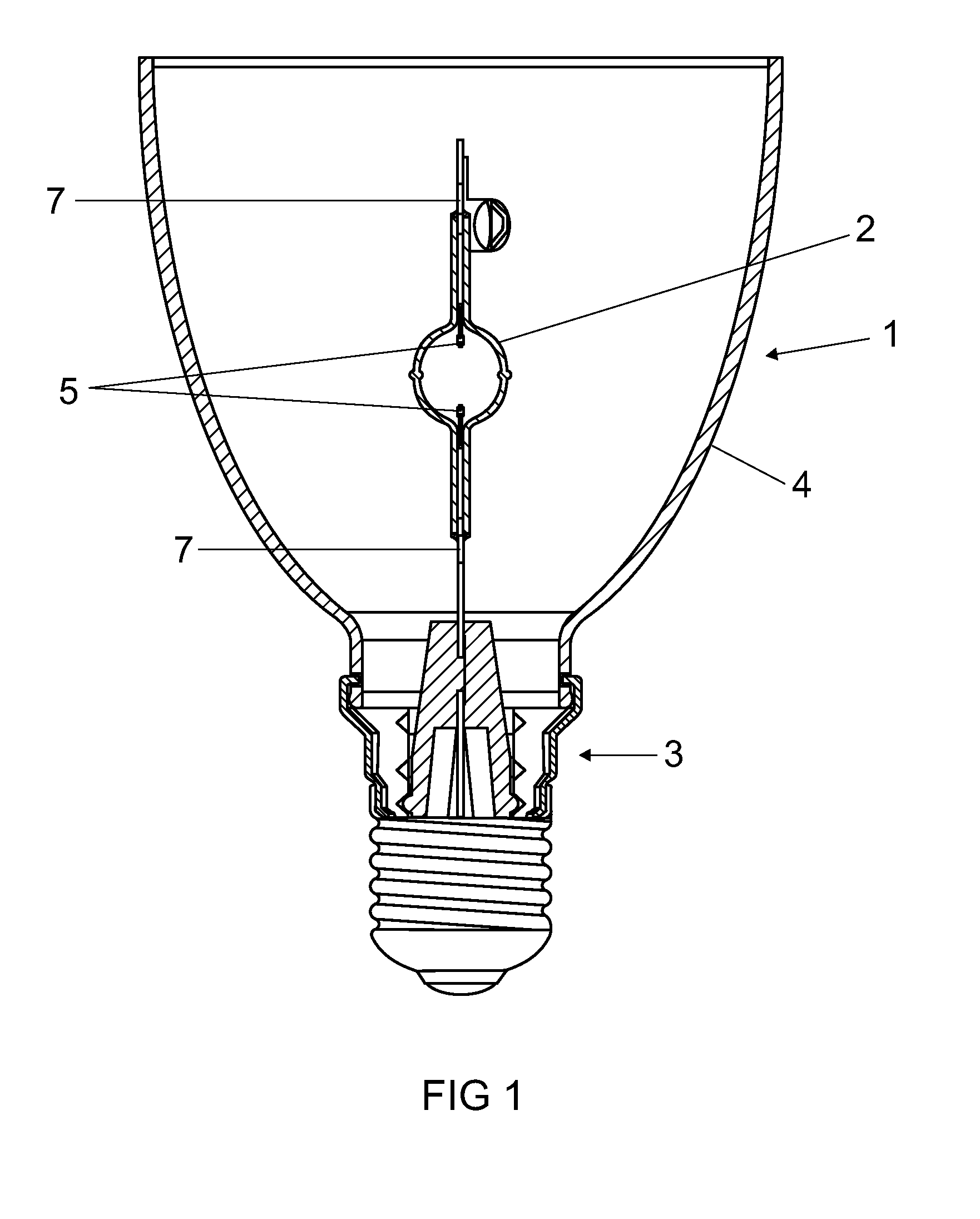
[0033]FIG. 1 schematically shows a reflector lamp 1. It has a ceramic discharge vessel 2, which is fastened in a base 3, and has two electrodes 5 in the discharge volume. Feed-throughs 7 project from the discharge vessel. A reflector 4, in which the discharge vessel is arranged axially, is fastened on the base. The discharge volume contains a fill, typically of metal halides and mercury.

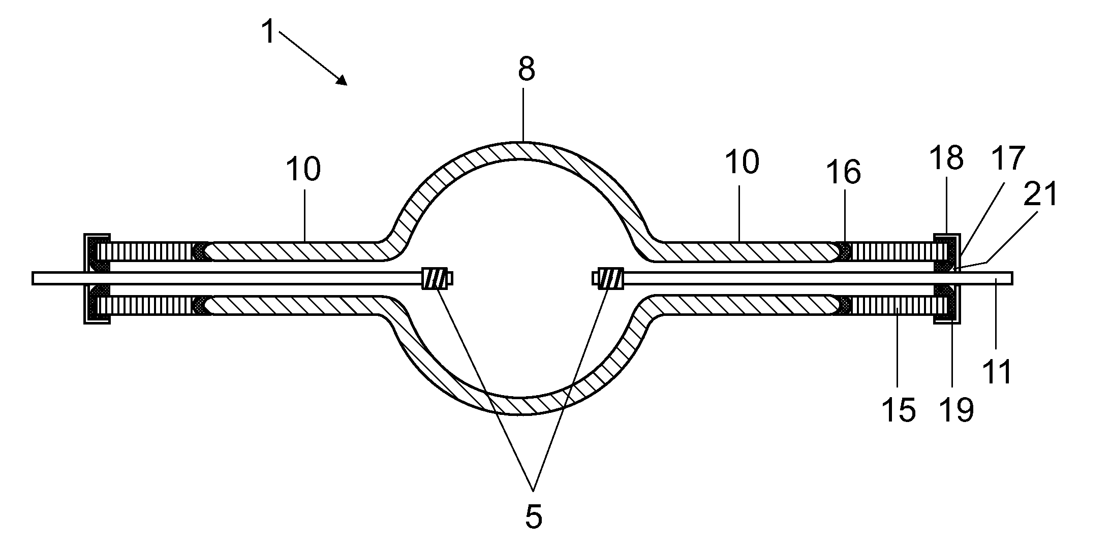
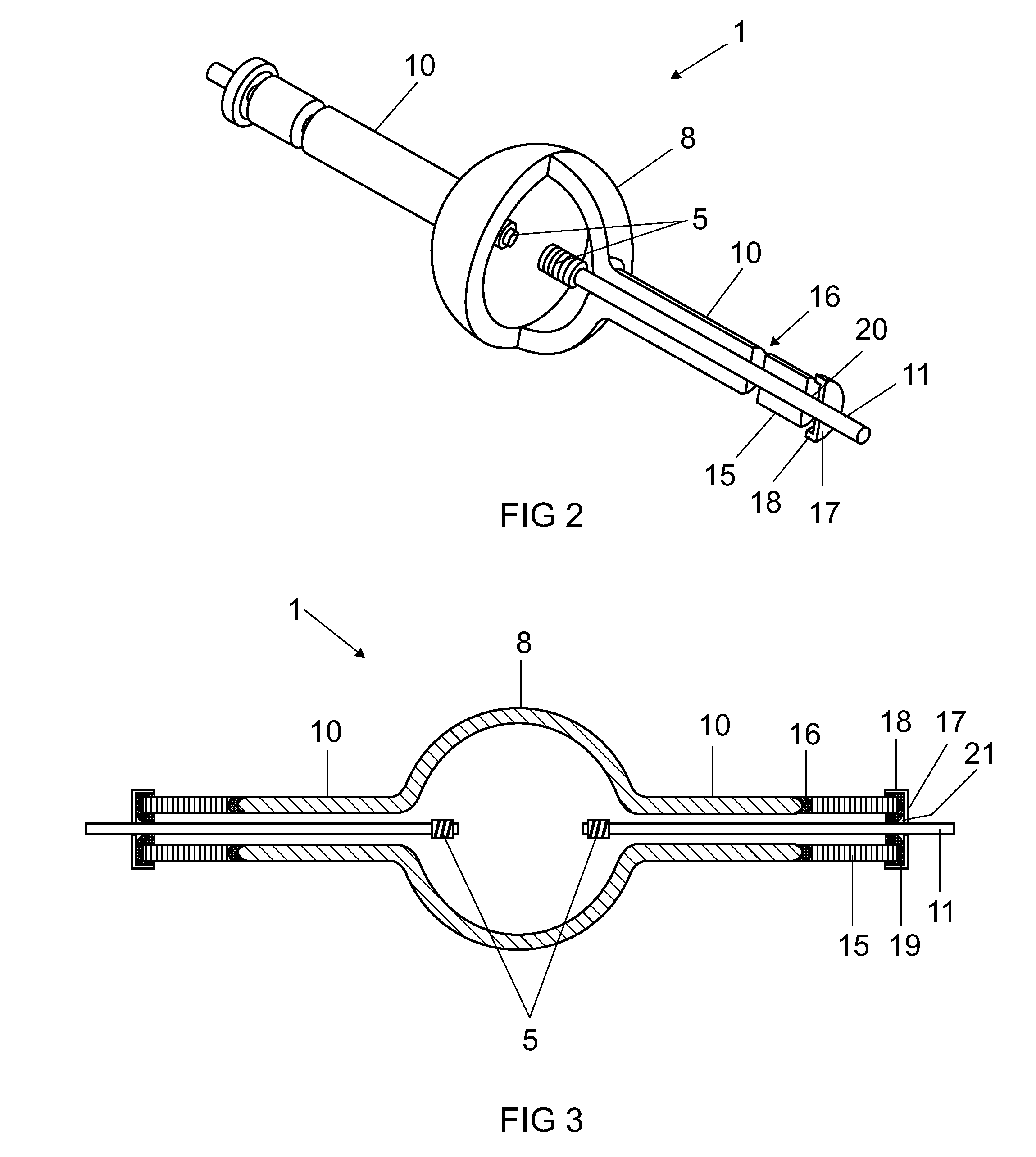
[0034]FIG. 2 shows the discharge vessel 2, which is essentially produced from Al2O3 and has a bulging central part 8 in which electrodes and a fill of metal halides are accommodated. Capillaries10 integrally adjoin the central part. Feed-throughs 11, for example consisting of Mo pins or configured in several parts as known per se, are fed into these capillaries and the shafts of the electrodes are respectively welded to them. All that is essential, however, is that the rear end of the feed-through is an Mo pin. It has a diameter of typically 1 mm. The capillary 10 is followed by a cermet tube 15 cons...


PUM

PropertyMeasurementUnit
Thicknessaaaaaaaaaa
Shrinkageaaaaaaaaaa
Thicknessaaaaaaaaaa

Abstract

A high-pressure discharge lamp may include a ceramic discharge vessel and a longitudinal axis, with electrodes respectively being led out from the discharge vessel by means of a feed-through via capillaries, wherein a tubular cermet part, which consists of individual layers of different composition layered axially in succession, is fitted on the capillary, each layer containing Mo and Al2O3, the proportion of Mo in the first layer facing toward the capillary being from 3 to 15 vol. % and in the last layer being from 85 to 97 vol. %, and a molybdenum cover cap, the cover cap being welded to the feed-through and the cover cap being connected to the cermet part by means of solder containing metal, and the connection between the capillary and the cermet part being established by means of high-melting glass solder or sinter-active Al2O3 powder.

Description

TECHNICAL FIELD[0001]The invention is based on a high-pressure discharge lamp according to the preamble of claim 1.PRIOR ART[0002]U.S. Pat. No. 5,861,714 and U.S. Pat. No. 5,742,123 disclose a high-pressure discharge lamp in which a ceramic discharge vessel uses an axially layered cermet part for sealing at its ends.[0003]In U.S. Pat. No. 5,742,123, a tungsten rod having a screw thread is fitted into a cermet part, the individual layers of which increase outward in their thickness. A platinum solder covers a flange on the cermet part. The number of layers is about 10. The first layer is placed directly onto the end of the discharge vessel, and the last layer is hermetically connected to the flange and the tungsten rod by means of the platinum solder.[0004]In U.S. Pat. No. 5,861,714, the sealing between the last layer and the feed-through is produced by direct sintering and optionally assistance by means of glass solder. In both cases, the cermet parts are difficult to produce. The l...

Claims


Application Information

Patent Timeline
IPC IPC(8): H01J61/36C04B37/02
CPCH01J9/323H01J61/366C04B35/117C04B2235/404B22F2999/00C22C29/12C22C32/0031B22F2998/10C22C1/051B22F1/0074B22F3/22B22F5/006B22F7/06B22F5/106B22F2207/03B22F1/107
Inventor HUETTINGER, ROLANDJUENGST, STEFANKOTTER, STEFANPHAM GIA, KHANHWALTER, STEFFEN
Owner OSRAM GMBH
Why Eureka
Try Eureka