Eureka AIR delivers breakthrough ideas for toughest innovation challenges, trusted by R&D personnel around the world.

Read disturb-free SMT reference cell scheme

a reference cell and scheme technology, applied in the field of smt magnetic random access memory (smtmram) cells, can solve the problems of unwanted cell switching, inability to compare, and increase the power consumption of the circui

Inactive Publication Date: 2010-12-02
HEADWAY TECH INC
View PDF15 Cites 19 Cited by
  • Summary
  • Abstract
  • Description
  • Claims
  • Application Information

AI Technical Summary

Benefits of technology

[0024]A first object of this invention is to provide a STM-MTJ reference cell circuit configuration for use in an MRAM device that is robust against read-induced resistance changes.
[0025]A second object of the present invention is to provide such a reference cell circuit configuration that is simple and easy to implement.
[0026]A third object of the present invention is to provide the fabrication structure that will effectively implement the circuitry of the reference cell.

Problems solved by technology

The fact that such an array of crossed word and bit lines can produce unwanted cell switching is a general problem associated with the use of externally generated magnetic fields to switch MRAM cells.
Another problem associated with the use of externally generated magnetic fields to produce switching is the problem of scaling, which is to say that as the cells become smaller so must the current carrying lines and this requires the passage of higher currents through lines of greater resistance, increasing the power consumption of the circuit.
Unfortunately, even though the read current through an SMT-MTJ cell is less than the write current, there is still a probability that the read current will produce sufficient torque transfer to change the polarity of the cell free layer.
If this occurs (or has already occurred), the comparison is useless, because of the undetected error in the content of the reference cell.
Moreover, once such an error has been introduced into the reference cell, all subsequent measurements based on comparison with the reference cell will be in error.
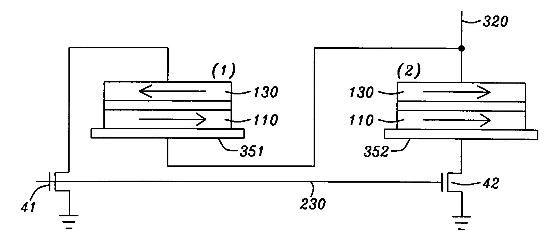
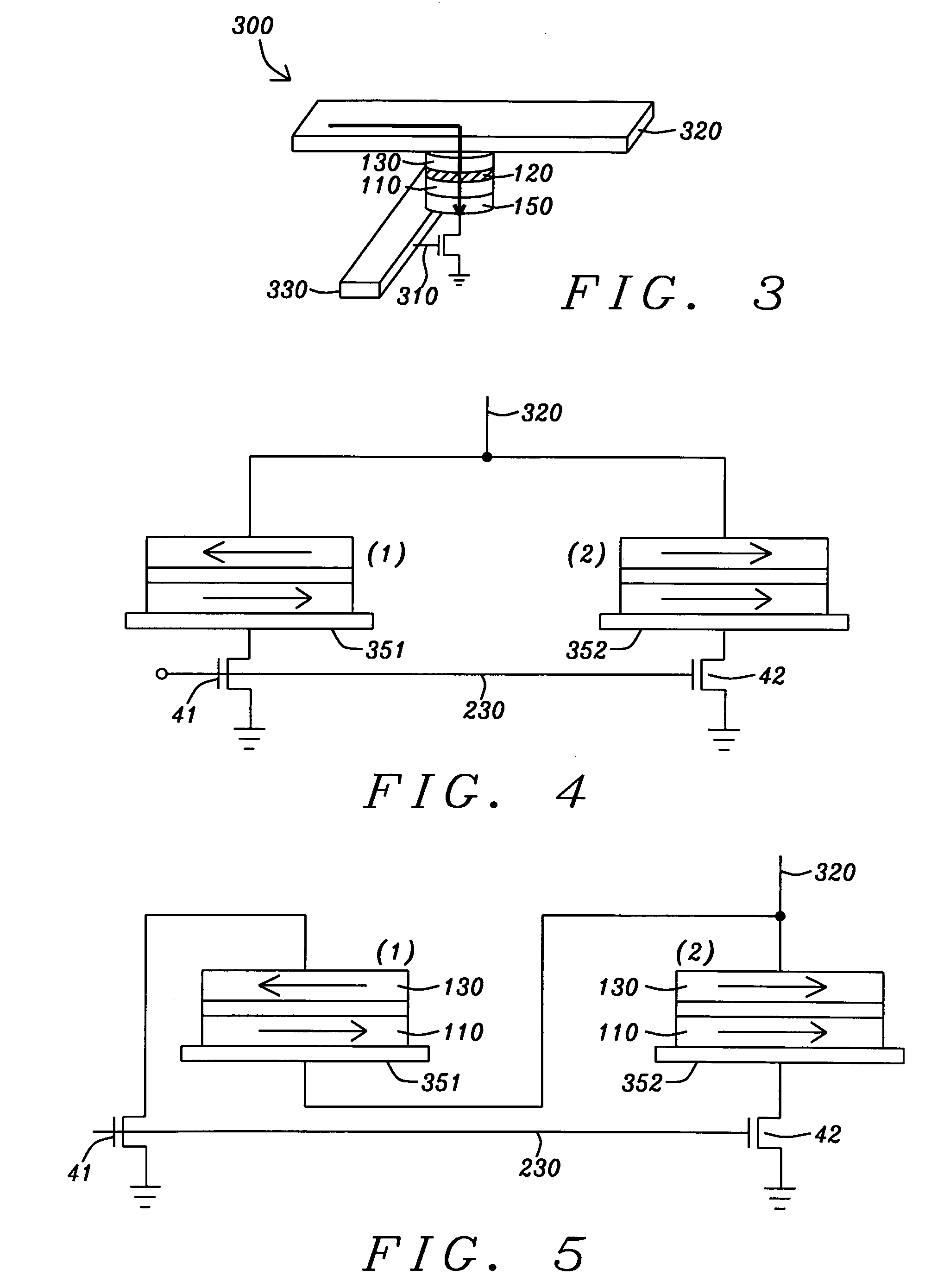
The physics of SMT is such that the direction of the current in SMT MTJ cell (2) will maintain the parallel configuration of magnetizations and keep (2) at Rmin, but there is the possibility of changing cell (1) from Rmax to Rmin, which would lead the reference cell configuration to fail in its purpose.
Although the prior art cited above teaches various methods to mitigate failure of a reference cell, none of that art discloses a method that is simple and easy to implement and will eliminate or sharply reduce the effect of a read operation on the resistance state of an SMT-MTJ cell.

Method used


Image

  • Read disturb-free SMT reference cell scheme
  • Read disturb-free SMT reference cell scheme
  • Read disturb-free SMT reference cell scheme

Examples


Embodiment Construction

[0035]The preferred embodiment of the present invention is a reference cell configuration that is resistant to changes in magnetization direction as a result of read operations. Referring to FIG. 5, there is shown, schematically, the reference cell configuration. It is formed as an interconnection of two STM MTJ cells, with one cell (2) in a parallel magnetization state of minimum resistance, Rmin, and the other cell (1) in an antiparallel magnetization state of maximum resistance, Rmax. The reference bit line (320) is connected to the free layer of cell (2) but to the fixed layer of cell (1) at (351). When a voltage to word line (230) opens read transistors (41) and (42), electrons flow through cell (2) from the fixed layer towards the free layer, but they flow through cell (1) from the free layer towards the fixed layer. As a result, the electrons flowing through cell (2) are polarized along the direction of the fixed layer, but they exert very little torque on the magnetization o...


PUM


Abstract

We describe a reference cell structure for determining data storing cell resistances in an SMT (spin moment transfer) MTJ (magnetic tunneling junction) MRAM array by comparing data cell currents with those of the reference cell. Since the reference cell also utilizes spin moment transfer (SMT) magnetic tunneling junction (MTJ) cells, there would ordinarily be the danger that the act of reading the reference cell could change its magnetization orientations and be a source of error for subsequent comparisons. Therefore the present invention describes a new circuit arrangement for the reference cell that directs read currents through two SMT MTJ cells in opposite directions so that the transfer of spin moments cannot affect the relative magnetization directions of the cells.

Description

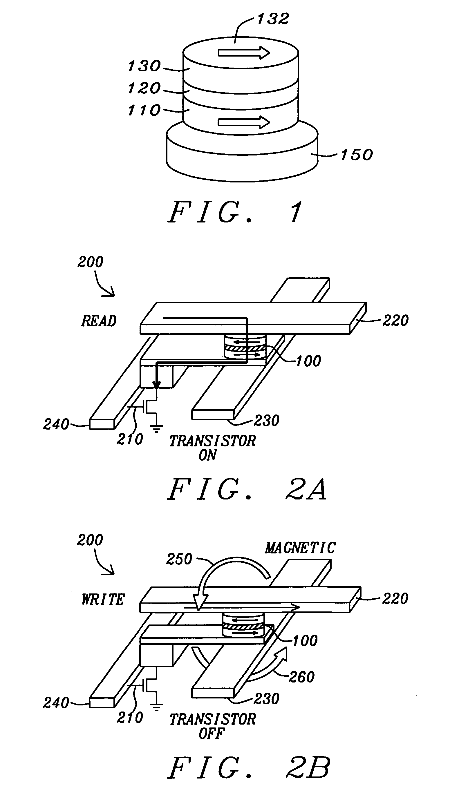
BACKGROUND OF THE INVENTION[0001]1. Field of the Invention[0002]This invention relates generally to a spin moment transfer (SMT) magnetic random access memory (SMT-MRAM) cell formed in a magnetic tunneling junction (MTJ) configuration. In particular, it relates to the use of such a cell as a reference cell in a manner that eliminates disturbance of the cell's resistance state by the act of reading it.[0003]2. Description of the Related Art[0004]The conventional magnetic tunneling junction (MTJ) device is a form of ultra-high magnetoresistive (MR) device in which the relative orientation of the magnetic moments of parallel, vertically separated magnetized layers, controls the flow of spin-polarized electrons tunneling through a very thin dielectric layer (the tunneling barrier layer) formed between those layers.[0005]Referring to FIG. 1 there is shown a highly schematic illustration of a prior art MTJ cell that, for the purposes of the following descriptions, can be either a standard...

Claims


Application Information

Patent Timeline
IPC IPC(8): G11C11/00G11C7/02H01L21/00G11C11/14
CPCG11C7/02G11C11/1659G11C11/1673G11C11/161G11C11/1675
Inventor WANG, POKANGYANG, HSU KAI
Owner HEADWAY TECH INC
Why Eureka
Eureka Blog
Learn More