Method, apparatus and program for image processing and method and apparatus for image synthesizing

a technology of image processing and apparatus, applied in the field of image processing technology, can solve the problems of inability to accurately inability to use techniques to separate light into specular reflection components and diffuse reflection components, etc., to achieve the effect of accurately separating the image of each pixel

Active Publication Date: 2010-12-02
PANASONIC CORP
View PDF15 Cites 43 Cited by
  • Summary
  • Abstract
  • Description
  • Claims
  • Application Information

AI Technical Summary

Benefits of technology

[0039]According to the image processing method of the present invention, two different kinds of information that are polarization information and color information are used, thus making it possible to accurately separate the image of each pixel into a specular reflection component and a diffuse reflection component. Also, if such a technique for separating an image into multiple components using the polarization information and the color information as two different kinds of information is used to estimate parameters in a model-based image synthesizing method, the image can be synthesized to produce a high-fidelity object's image.

Problems solved by technology

That problem prevents the specular / diffuse reflection component separating technique using the polarization information from achieving sufficiently high accuracy.
According to that technique, however, unless the object color vector of the object is known, the light cannot be separated into specular and diffuse reflection components unambiguously.
For that reason, such a technique cannot be used to separate light into a specular reflection component and a diffuse reflection component accurately.
And it is known that such inaccurate separation into specular and diffuse reflection components should be a grave issue when a model-based image synthesis, which is adopted in the fields of digital archiving and augmented reality, needs to be carried out.

Method used


Image

  • Method, apparatus and program for image processing and method and apparatus for image synthesizing
  • Method, apparatus and program for image processing and method and apparatus for image synthesizing
  • Method, apparatus and program for image processing and method and apparatus for image synthesizing

Examples


embodiment 1

[0089]First of all, the Configuration of an Image processing apparatus as a first specific preferred embodiment of the present invention will be outlined.

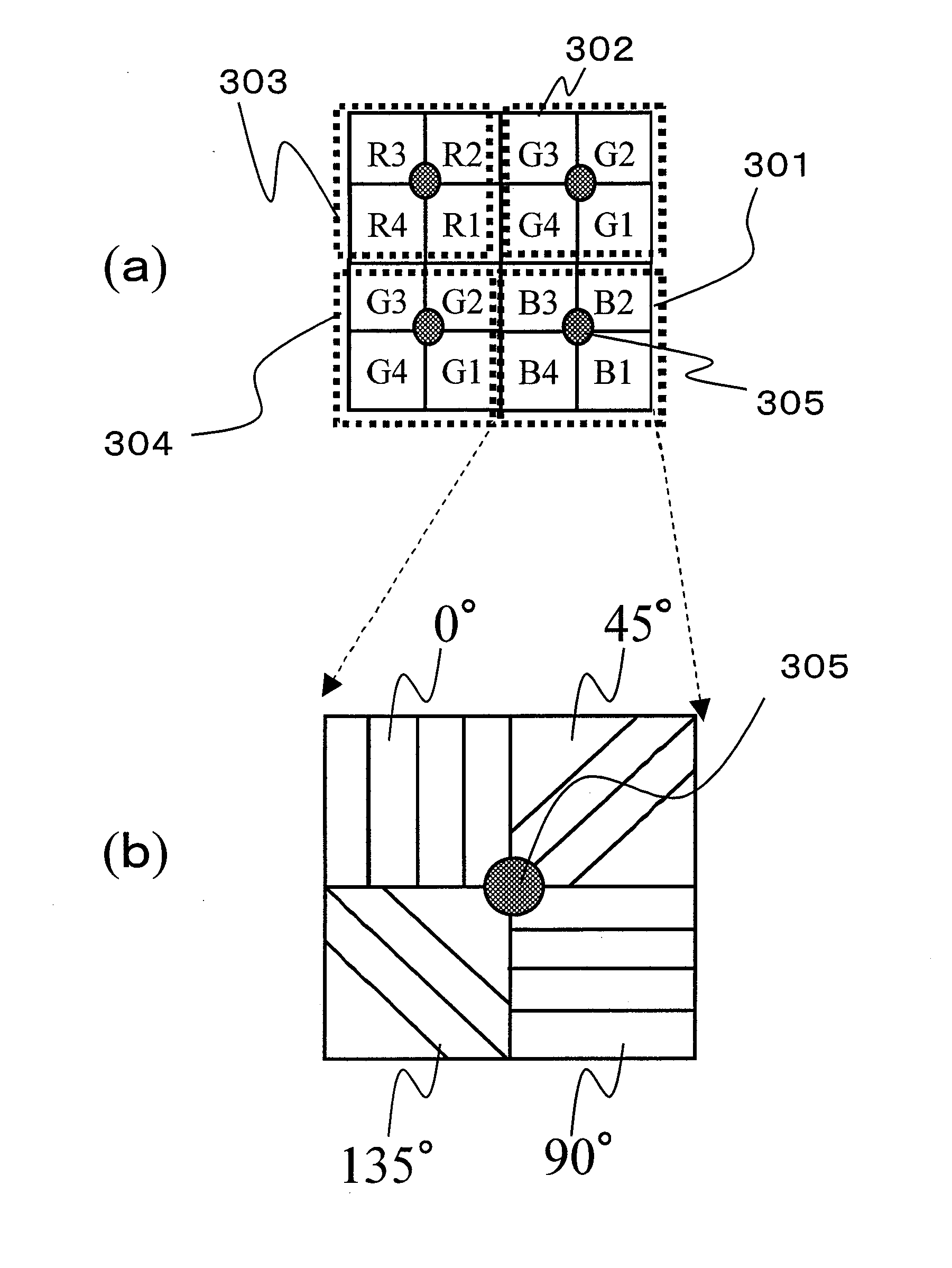
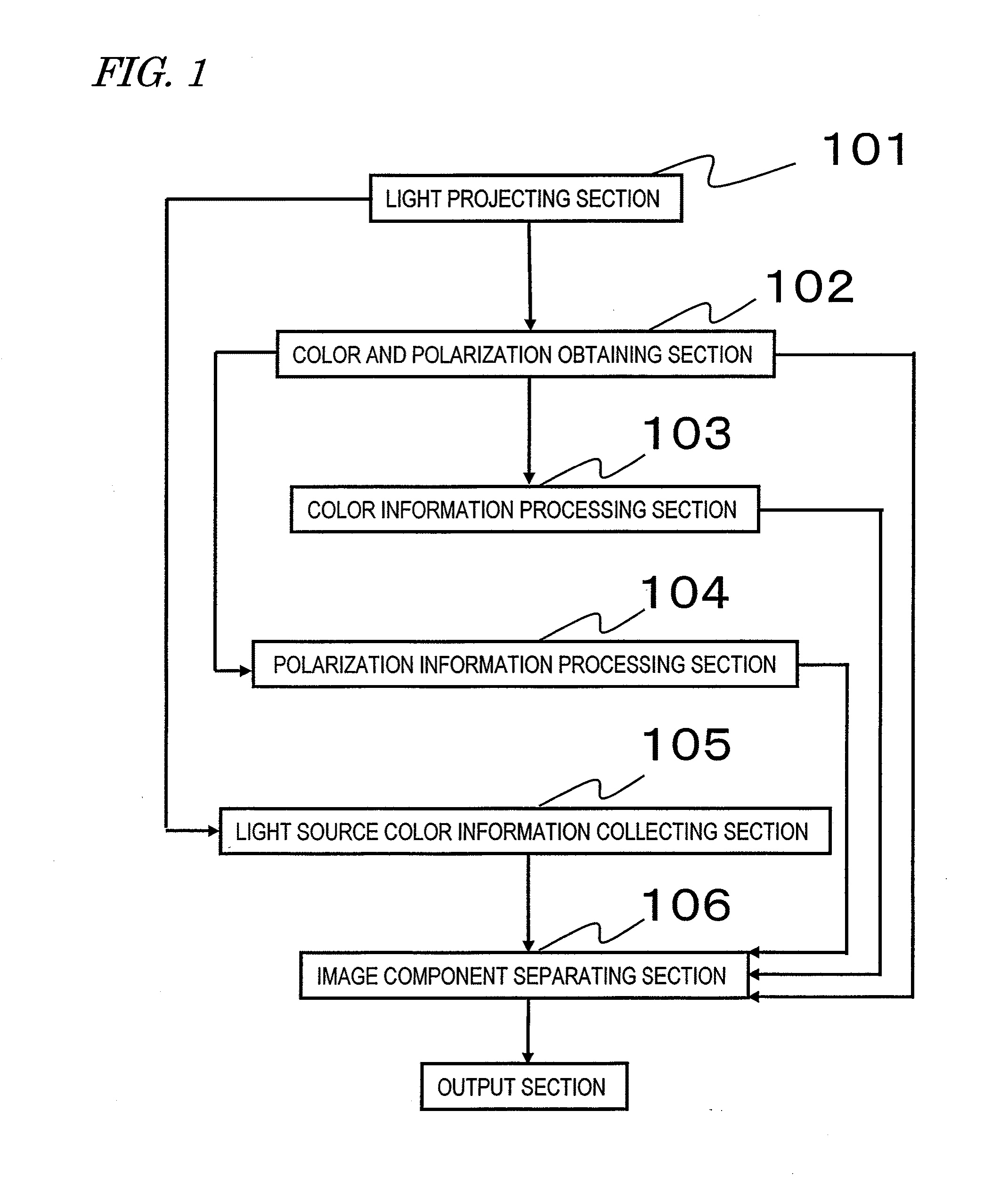
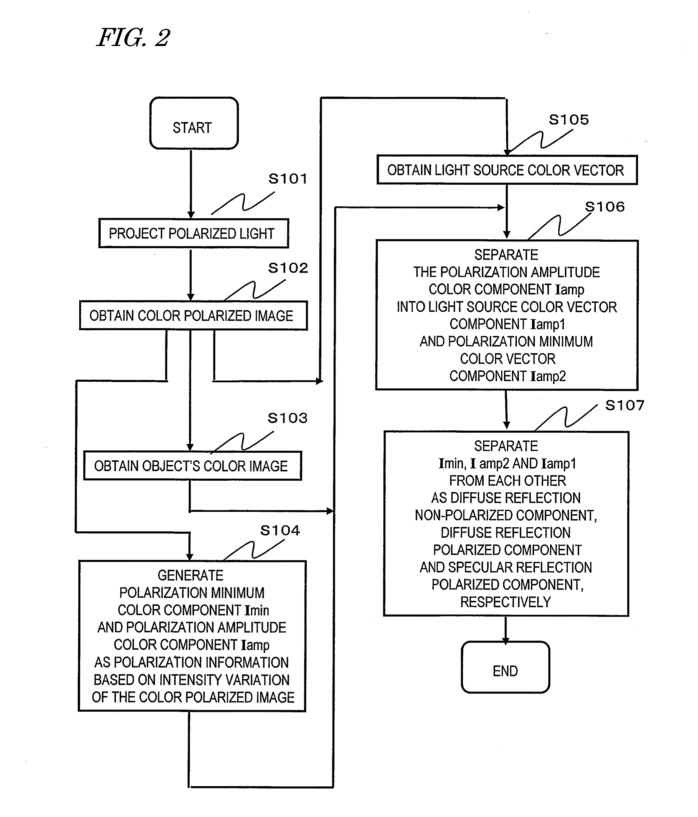
[0090]FIG. 1 is a block diagram illustrating an image processing apparatus as a first preferred embodiment. This image processing apparatus is designed to capture an object's image and separate the object's image into multiple components. The apparatus includes: a light projecting section 101 for projecting linearly polarized light toward the object; a color and polarization obtaining section 102 for getting a color polarized image of the object by receiving light that has been transmitted through a polarizer with three or more different polarization principal axis directions at a color filter; a color information processing section 103 for generating a color image based on the image obtained by the color and polarization obtaining section 102; a polarization information processing section 104 for generating, based on the image obt...

embodiment 2

[0202]FIG. 29 is a block diagram illustrating an image separation system as a second specific preferred embodiment of the present invention. In FIG. 29, the same element as what is also shown in FIG. 1 is identified by the same reference numeral as its counterpart's and a detailed description thereof will be omitted herein. The difference from the first preferred embodiment is that the projector 107 and the image processing apparatus 108 are separated from each other according to this preferred embodiment. FIG. 30 is a flowchart illustrating the procedure of image separation processing steps to be done by the image processing apparatus of this preferred embodiment. In FIG. 30, the same processing step as what is also shown in FIG. 2 is identified by the same reference numeral as its counterpart's and a detailed description thereof will be omitted herein to avoid redundancies. Furthermore, FIG. 31 illustrates an exemplary configuration for a camera with the image processing apparatus...


PUM


Abstract

An image processing apparatus captures an object's image and separates the object's image into multiple components. The apparatus includes: a light projecting section 101 for projecting light emitted from a light source toward the object; a color and polarization obtaining section 102 for getting a color polarized image of the object; a polarization information processing section 104 for generating color and polarization information based on an association between the intensity of the light that has been transmitted through a polarizer with three or more polarization principal axis directions and the polarization principal axis directions for each of unit pixels that form the color polarized image; a light source color information collecting section 105 for collecting color information of the light source; and an image component separating section 106 for separating the color image into multiple components based on the polarization information and the color information of the light source.

Description

TECHNICAL FIELD[0001]The present invention generally relates to an image processing technology and more particularly relates to a technique for increasing the accuracy of image division that needs to be done to obtain information about the shape of an object and to synthesize an image.BACKGROUND ART[0002]It is known that the “appearance” of an object is determined by a number of components including a specular reflection component, which is a part of incoming light that has been reflected from the object and then sensed as a sort of “gloss”, and a diffuse reflection component, which is sensed after the incoming light has been scattered a number of times inside the object. That is to say, every image of an object that we view daily is normally the sum of various components of the light that strike our eyes after having gone through multiple different courses from the object. And examples of those components include the “specular reflection component” and the “diffuse reflection compo...

Claims


Application Information

Patent Timeline
Patent Type & Authority Applications(United States)
IPC IPC(8): G06K9/00
CPCG06T2207/10024H04N9/045G06T7/11H04N23/84H04N25/134
Inventor SATOKANAMORI, KATSUHIRO
Owner PANASONIC CORP
Why Eureka
Try Eureka