Solid state light source based on hybrid waveguide-down-converter-diffuser

a light source and hybrid technology, applied in the field of solid-state light sources, can solve the problems of virtually none of the emerging light sources meeting these requirements, led-based lighting has not been cost-competitive in most markets, and the total cost of lighting is not only the cost of lamps, so as to facilitate the increase of monochromatic light outcoupling, increase optical coupling, and high light outcoupling efficiency

Active Publication Date: 2010-12-02
RGT UNIV OF MICHIGAN
View PDF11 Cites 14 Cited by
  • Summary
  • Abstract
  • Description
  • Claims
  • Application Information

AI Technical Summary

Benefits of technology

[0004]Currently, the United States collectively spends on the order of a trillion dollars annually on electricity for lighting alone—in fact, a quarter of most buildings' electricity usage is for lighting. Thus, even a modest increase in lighting efficiency can result in tremendous money savings and benefits to the environment. Solid state light emitting devices (LEDs or organic LEDs) potentially can replace existing incandescent and fluorescent lamps as a more energy-efficient lighting solution, offering luminous efficiencies in excess of 100 lm / W.
[0024]To overcome the deficiencies of conventional solid-state lighting, the principles of the present teachings provide an approach that combines well-established technologies in a novel, effective way. As illustrated in FIGS. 1 and 2, a solid state light source 10, according to the principles of the present teachings, is provided having a light pump 12 and a waveguide assembly 14 operably coupled to light pump 12 for communication of light energy therebetween. Specifically, the present teachings provide a system wherein, in some embodiments, the output of blue LEDs is coupled to an optical waveguide or waveguide assembly comprising a waveguide core and a waveguide cladding, whereby the waveguide core has a higher refractive index compared to the waveguide cladding. The outer surface of the waveguide can be coated with wavelength conversion materials (e.g. fluorescent dyes, phosphors, and quantum dots). By properly shaping the waveguide, uniformly leaked blue light excites the wavelength conversion materials to generate a white light. A primary advantage of the present teachings compared to conventional systems includes (i) the optical intensity (optical power per unit area) of the blue excitation is considerably lower, enabling the use of wider range of wavelength conversion materials, and (ii) the form factors (size and shapes) of the lighting devices can be easily changed simply by changing the form factor of the waveguides and is not restricted by the placement of the wavelength conversion materials (e.g. elongated lighting devices for replacement use in fluorescent fixtures).
[0029]It has been found that the total light outcoupling efficiency of the present teachings are very high. This can be attributed, in part, due to the acceptance angle (+ / −30 degrees) of the waveguide core 16 to the LED source 12. Thus, the emission cone of the LED source 12 can also be narrow, which in turn facilitates increase in the monochromatic light outcoupling from the LED by means of dielectric stacks, photonic crystals, and other means. It has also been found that the surface of the cladding / barrier layer(s) can also be roughened to increase the optical coupling to air. Importantly, the color rendering index (CRI) of this assembly 10 can be tuned very precisely by the selection of down-converters from a wide variety of material systems—e.g. inorganic phosphors, fluorescent and phosphorescent organic dyes, luminescent polymers, etc.
[0030]The waveguide 14 acts to lower the excitation intensity and reduces the concentration of the down-converter (e.g. a molecular dye) by doping it into an inert matrix (e.g. PMMA, parylene, etc). This increases the operational lifetime of the down-converter, which mitigates common degradation mechanisms in conventional white LEDs.
[0031]The waveguide 14 can act as an excellent diffuser for the light escaping the assembly, potentially lowering overall fixture / luminaire costs.
[0034]To address this issue and to uniformly generate the white light throughout the entire device 10, in some embodiments of the present teachings the structure of the waveguide 14 is such that additional radiation loss is purposefully introduced via the intentional bending of the waveguide 14 as illustrated in FIGS. 6 and 7. The bending of the waveguide 14 enable some of the light ray guided by the waveguide 14 to leak out because the total internal reflection condition is no longer satisfied. By properly controlling the layout of the waveguide 14, the bending loss can increase along the waveguide length to compensate for the exponential decay of power (i.e. light intensity). Because the bending loss only depends on the bending radius for a particular waveguide structure, the radius of waveguide 14 can be varied continuously as illustrated in FIGS. 6 and 7 to achieve uniform white light output. In some embodiments, as illustrated in FIG. 6, waveguide 14 is structured as an upwardly extending, progressively tightening coil in which the internal bending radius is progressively increasing to offset the loss of light intensity. In this embodiment, the shape thereof is conducive to replacing existing lighting fixtures for incandescent light. In some embodiments, as illustrated in FIG. 7, waveguide 14 is structured as a helix having a generally constant outside diameter, but an increasing pitch in which the internal bending radius is again progressively increasing to offset the loss of light intensity. In this embodiment, the cylindrical shape thereof is conducive to replacing existing lighting fixtures for fluorescent light and can be done by wrapping the waveguide on a cylindrical mold. In some embodiments, the wrapping of the waveguide can be performed on a mold on which a reflection layer (e.g. metal) can be coated to increase the out-coupling efficiency.

Problems solved by technology

However, the cumulative cost of lighting comprises not only the electricity cost, but also the cost of the lamp.
Thus far, LED-based lighting has not been cost-competitive in most markets (e.g. indoor general lighting).
To date, virtually none of the emerging light sources satisfy these requirements.
Due to expensive manufacturing processes (e.g. epitaxy) and non-compatible blue / green and red LEDs materials, current white LEDs are predominantly based on blue LEDs coated with yellow phosphors.
This approach, however, generates very poor CRI output (ca.
Hence external lens and diffusers are required, which lead to additional manufacturing and assembly costs.
Nevertheless, several significant technical and scientific challenges must be overcome before they become commercially viable for SSL applications.
Some of these challenges include: 1. high cost of substrates (calculations suggest that the entire OLED must cost less than $100 / m2); 2. low light outcoupling efficiency (calculations suggest that the light extraction efficiency should exceed 50%); 3. poor operational lifetime of blue-emitting materials, and 4. high cost of encapsulation (especially in the context of reel-to-reel manufacturing on flexible substrates).

Method used


Image

  • Solid state light source based on hybrid waveguide-down-converter-diffuser
  • Solid state light source based on hybrid waveguide-down-converter-diffuser
  • Solid state light source based on hybrid waveguide-down-converter-diffuser

Examples


Embodiment Construction

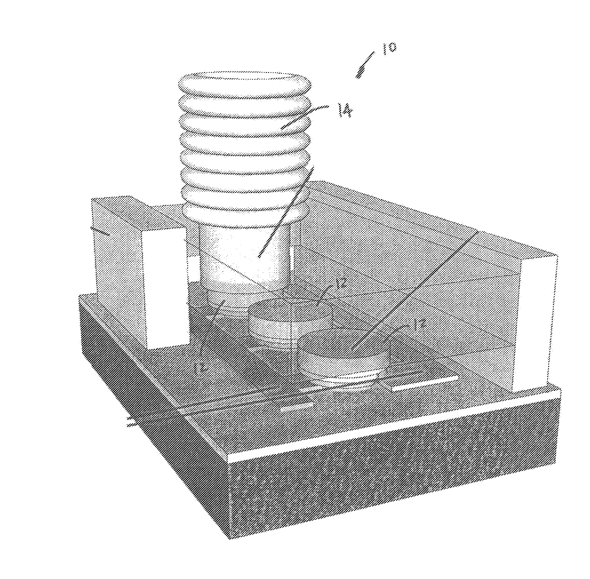
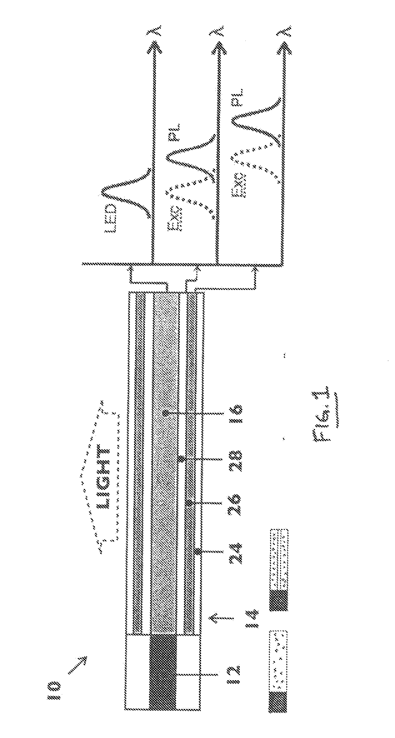
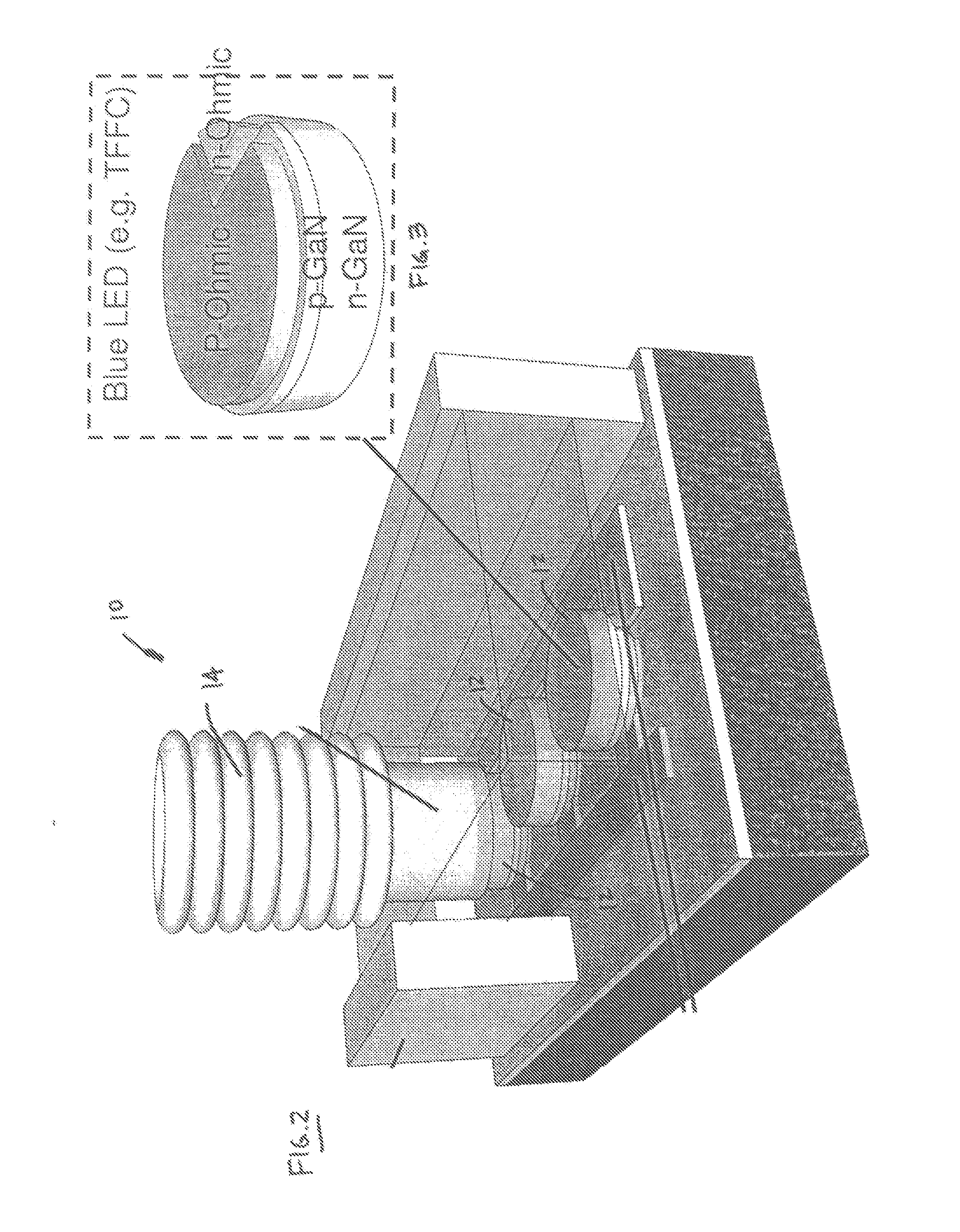
[0021]Example embodiments will now be described more fully with reference to the accompanying drawing. Example embodiments are provided so that this disclosure will be thorough, and will fully convey the scope to those who are skilled in the art. Numerous specific details are set forth such as examples of specific components, devices, and methods, to provide a thorough understanding of embodiments of the present disclosure. It will be apparent to those skilled in the art that specific details need not be employed, that example embodiments may be embodied in many different forms and that neither should be construed to limit the scope of the disclosure.

[0022]The terminology used herein is for the purpose of describing particular example embodiments only and is not intended to be limiting. As used herein, the singular forms “a”, “an” and “the” may be intended to include the plural forms as well, unless the context clearly indicates otherwise. The terms “comprises,”“comprising,”“includi...


PUM


Abstract

A solid state light source comprising a light pump outputting light energy; a waveguide optically coupled to the light pump source for receiving the light energy; and a down-converter for converting the light energy from the waveguide to a lesser light energy.

Description

CROSS-REFERENCE TO RELATED APPLICATIONS[0001]This application claims the benefit of U.S. Provisional Application No. 61 / 182,171, filed on May 29, 2009. The entire disclosure of the above application is incorporated herein by reference.FIELD[0002]The present disclosure relates to solid state light sources and, more particularly, relates to a solid state light source based on hybrid waveguide down-converter diffusers.BACKGROUND AND SUMMARY[0003]This section provides background information related to the present disclosure which is not necessarily prior art. This section also provides a general summary of the disclosure, and is not a comprehensive disclosure of its full scope or all of its features.[0004]Currently, the United States collectively spends on the order of a trillion dollars annually on electricity for lighting alone—in fact, a quarter of most buildings' electricity usage is for lighting. Thus, even a modest increase in lighting efficiency can result in tremendous money sav...

Claims


Application Information

Patent Timeline
Patent Type & Authority Applications(United States)
IPC IPC(8): G02B6/26H01L33/58
CPCG02B6/0003G02B6/0038G02B6/0041H01L33/505G02B6/0001
Inventor KU, PEI-CHENGSHTEIN, MAX
Owner RGT UNIV OF MICHIGAN
Why Eureka
Try Eureka