Multicolor imaging system

Inactive Publication Date: 2010-12-02
RICOH KK
View PDF21 Cites 45 Cited by
  • Summary
  • Abstract
  • Description
  • Claims
  • Application Information

AI Technical Summary

Benefits of technology

[0012]The present invention aims to provide a multicolor imaging system which comprises photoreceptors with drive elements driving the photoreceptors to generate a fluctuation in their rotary velocity in the same cycle as that of a transfer unit and which can generate high-quality color images with l

Problems solved by technology

However, there is a problem in such a system including an intermediate transfer belt as a transfer element onto which toner images are transferred from four photoreceptor drums that a moving velocity of the intermediate transfer belt is changed due to eccentricity of a drive roller therefor or an error in engagement of drive gears, causing a color registration error in the toner images and degrading quality of generated images.
Further, when the ambient environment of the imaging system changes or the inner temperature of the system changes due to a continuous paper feed, a belt drive roller may expand or contract and the average moving velocity of the transfer belt may change, which causes extension or reduction of toner images in a sub scan direction and a color registration error in the toner images as well as degrades the quality of color images.
However, since in References 1 and 2 the intermediate transfer belt and the photoreceptor drums are driven by the same motor aiming for manufa

Method used


Image

  • Multicolor imaging system
  • Multicolor imaging system
  • Multicolor imaging system

Examples


first example

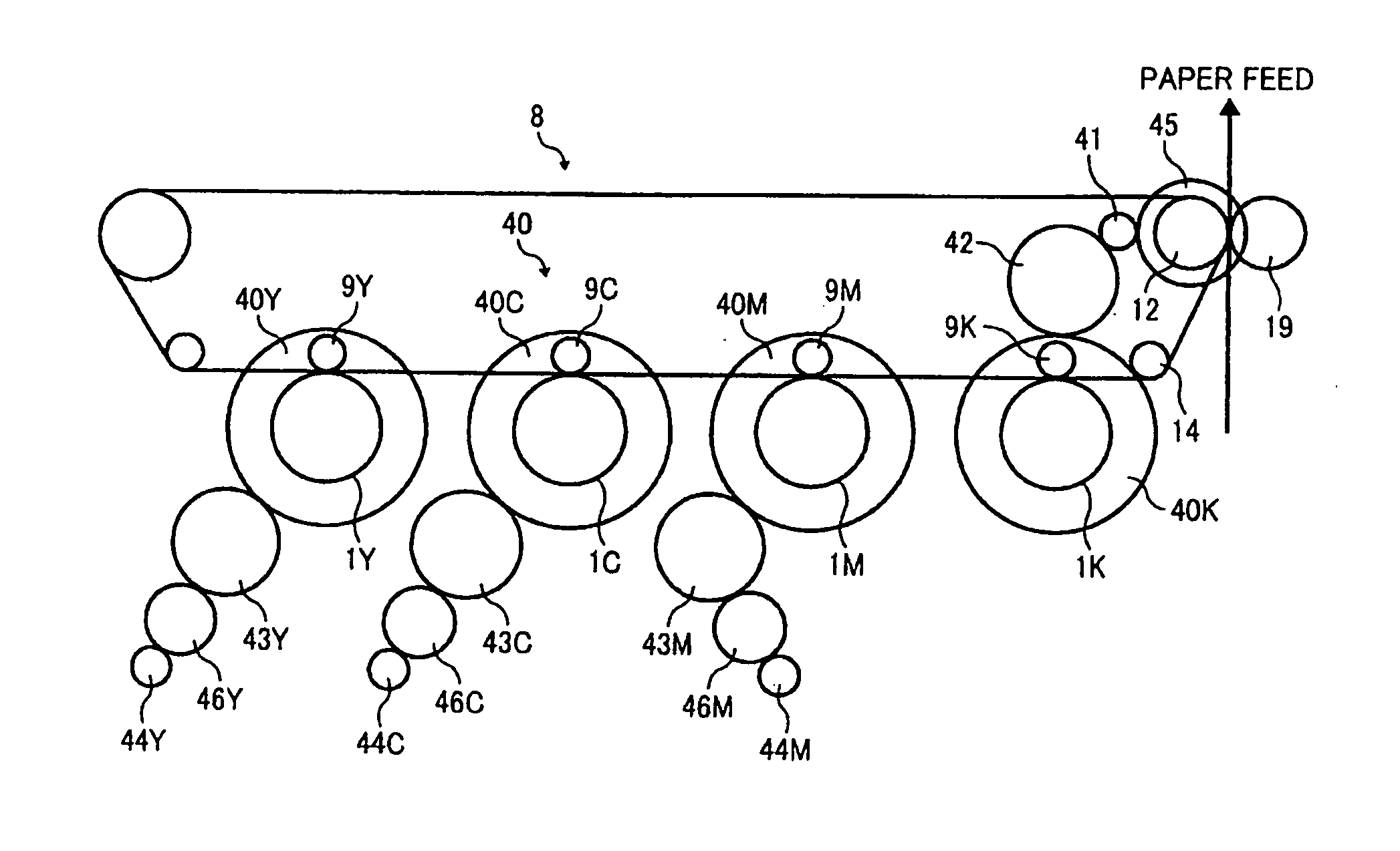
[0044]Referring to FIG. 3, the first example of a drive unit is described according to one embodiment of the present invention. The belt drive roller 12 for the intermediate transfer belt 8 (belt element) and the black photoreceptor drum 1K are rotated by drive force from a drive motor 41 (drive unit). Specifically, the drive motor 41 (or gear provided on the drive shaft thereof) is connected with the transfer belt drive gear 45 coaxial with the belt drive roller 12, to drive the intermediate transfer belt 8. It is also connected with the black drum drive gear 40K via an idle gear 42 to drive the black photoreceptor drum 1K. Meanwhile, the other color photoreceptor drums 1Y, 1M, 1C are driven by drum drive motors 44Y, 44M, 44C, respectively. In order to reduce color shifts in toner images on the intermediate transfer belt 8 due to velocity fluctuations of the drum drive gear 40K and the other drum drive gears 40Y, 40M, 40C, first phase adjusting gears 43Y, 43M, 43C and second phase ...

second example

[0049]The second example of the drive system in FIG. 4 is different from that of the first example in the connection of the black photoreceptor drum 40K, transfer belt drive gear 45, and drive motor 41. Specifically, in the second example the drive motor 41 is connected with the black photoreceptor drum 40K to drive it and driving of the black drum 40K is transmitted to the transfer belt drive gear 45 via idle gears 42, 42′ while in the first example the drive force of the drive motor 41 is directly transmitted to the transfer belt drive gear 45 and to the black drum gear 40K via the idle gear 42. The relations among the other drum drive gears, idle gears, and phase adjusting gears are the same as in the first example.

[0050]The idle gears 42, 42′ are set to have the same rotary cycle as that of the first phase adjusting gears 43Y, 43C, 43M while the transfer belt drive gear 45 is set to have the same rotary cycle as that of the second phase adjusting gears 46Y, 46C, 46M. Thus, the s...

third example

[0052]The drive system in the third example in FIG. 5 differs from that in the first example in that the other photoconductor drums than the photoreceptor drum 1K are driven by a single drive motor 44. As shown in the drawing, the drive motor 44 (gear provided on the drive shaft) is connected with a second phase adjusting gear 46 which is connected with the first phase adjusting gear 43. The phase adjusting gear 43 is connected with the drum drive gears 40C, 40M to drive the photoconductor drums 1C, 1M. Further, another first phase adjusting gear 43′ is provided between the drum drive gears 40C and 40Y to transmit driving of the drum drive gear 40C to the drum drive gear 40Y. The first phase adjusting gears 43, 43′ have the same rotary cycle as that of the idle gear 42 while the second phase adjusting gear has the same rotary cycle as that of the belt drive gear 45. This makes it possible to accurately adjust phases of rotary velocity fluctuations in the four photoreceptor drums and...


PUM


Abstract

A multicolor imaging system includes a controller which adjusts a phase difference in rotations of photoreceptors based on information detected by a rotary position detector, and drive elements for photoreceptors which generate a velocity fluctuation in the same cycle as that of a transfer unit. The controller is configured to concurrently adjust the phases of the photoreceptors and those of the drive elements so that a registration error in four color toner image on an intermediate transfer belt is reduced to a minimum.

Description

CROSS REFERENCE TO RELATED APPLICATION[0001]The present application is based on and claims priority from Japanese Patent Application No. 2009-133429, filed on Jun. 2, 2009, the disclosure of which is hereby incorporated by reference in its entirety.BACKGROUND OF THE INVENTION[0002]1. Field of the Invention[0003]The present invention relates to a multicolor imaging system such as a photocopier, a facsimile machine, or a printer which comprises a feed back controller to rotate a belt at a constant rotation rate.[0004]2. Description of the Related Art[0005]Recently, in the field of an imaging system such as a photocopier or a printer, there has been an increasing demand for not only higher speed printing but also higher quality color image generation along with the widespread use of imaging devices such as a digital camera. In order to satisfy such a demand, a tandem type color imaging system including respective imaging units for yellow, cyan, magenta, and black has been widely used. ...

Claims


Application Information

Patent Timeline
IPC IPC(8): G03G15/00G03G15/01
CPCG03G15/50G03G2215/0132G03G2215/0161G03G15/0131G03G15/0194
Inventor FUNAMOTO, NORIAKIEHARA, YASUHISANISHIKAWA, TETSUJIMAEHATA, YASUHIROYASUDA, JUNMURAKAMI, HIROAKI
Owner RICOH KK
Why Eureka
Try Eureka