Gear Cutting Machine

a cutting machine and gear technology, applied in the direction of gear teeth, gear teeth, gear-teeth manufacturing apparatus, etc., can solve the problems of limited grinding arm length, limited internal toothed arrangement maximum grindable width, and inability to use dressing devices

Inactive Publication Date: 2010-12-02
LIEBHERR VERZAHNTECHNIK GMBH
View PDF13 Cites 20 Cited by
  • Summary
  • Abstract
  • Description
  • Claims
  • Application Information

AI Technical Summary

Benefits of technology

[0005]It is therefore the object of the present invention to provide a gear cutting machine for the grinding of internal and external profiles with straight and slanting toothed arrangements which is equipped with a dressing unit for the external dressing and internal dressing of profiles and which avoids the disadvantages of the above-described gear cutting machines. Furthermore, a pivoting of the grinding tool into a basic position for the dressing thereof should no longer be necessary. It is likewise the object of the present invention to provide the skilled person with an improved method for the dressing of a grinding tool for an internal profile or an external profile.

Problems solved by technology

The disadvantage of this embodiment is the necessity of a pivot axle so that the position of the grinding disc at the time of dressing and at the time of grinding differ and the precision of the pivot bearing can thus enter into the grinding result.
A further disadvantage of this invention is the circumstance that the length of the grinding arm and thus the maximum grindable width of the internal toothed arrangement is limited by the pivot mechanism.
It is a disadvantage of this invention that the dressing device is only usable for the internal grinding head and the grinding angle of the grinding disc has to be moved back into a basic position for the dressing during the grinding process.

Method used


Image

  • Gear Cutting Machine
  • Gear Cutting Machine
  • Gear Cutting Machine

Examples


Embodiment Construction

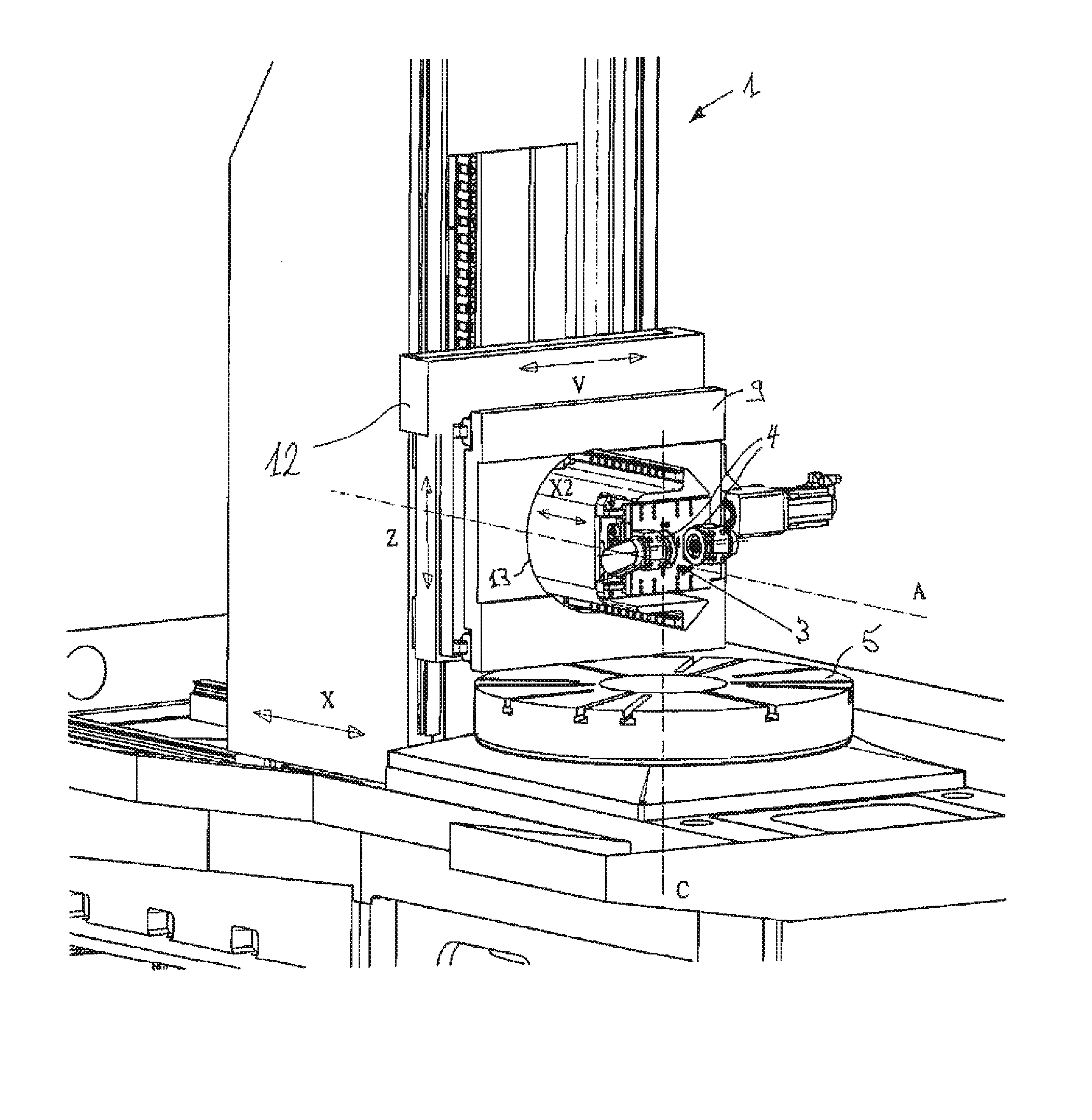
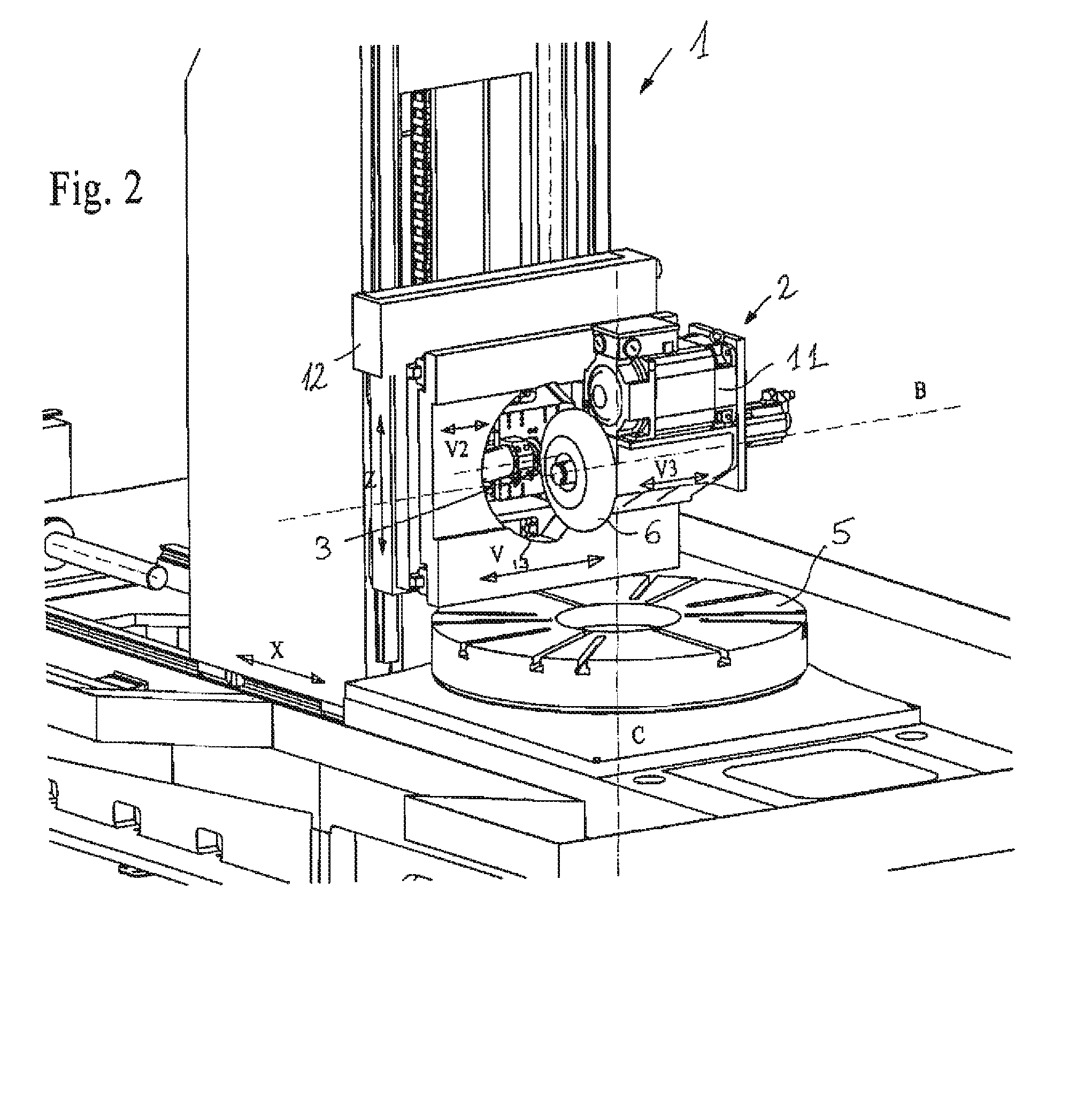
[0034]The general design of the gear cutting machine will be explained in more detail with reference to FIG. 1. It has a machine table 5 for the installation of a tool receiver and a workpiece can be clamped onto said machine table. The machine table 5 is in this respect rotatable about an axis C which is advantageously aligned in a perpendicular manner. Alternatively, however, horizontally aligned workpiece receivers can also be used. The gear cutting machine 1 furthermore has one or more installation surfaces 9 for the installation of a machining head 2, 7 (see FIG. 2 and FIG. 3 respectively). Either an external grinding head 2 for the machining of the external profile of a workpiece can be installed on the gear cutting machine 1 or an internal grinding head 7 for the machining of the internal profile of a further workpiece (see FIG. 2 and FIG. 3 respectively). One or more grinding tools 6, 8 can be clamped on the respective machining heads 2, 7. The grinding tools 6, 8 are in thi...


PUM

PropertyMeasurementUnit
degrees of freedomaaaaaaaaaa
rotationaaaaaaaaaa
axis of rotationaaaaaaaaaa

Abstract

The invention relates to a gear cutting machine for the grinding of external profiles and/or internal profiles of workpieces having at least one machining head which can be rotated about an axis and which has a grinding tool, and having a dressing unit. In accordance with the invention, the dressing unit is supported in the region of the pivot axis of the machining head such that it is pivotable about the common pivot axis together with the machining head and such that it can be moved along the pivot axis toward the grinding tool to be dressed.

Description

BACKGROUND OF THE INVENTION[0001]The present invention relates to a gear cutting machine for the grinding of internal profiles or external profiles of workpieces having a machining head, which is arranged on a pivotable installation surface and which provides a grinding tool, and having a dressing unit, in particular a common dressing unit, for the dressing of the grinding tool of an installed external or internal grinding head. A worm grinding wheel or a grinding disc can be used as the grinding tool here, for example.[0002]To achieve or to maintain an exact true running and the correct geometrical shape of the grinding tool, the grinding tool has to be shaped and sharpened at different intervals by means of dressing. In addition, the dressing serves to true and / or calibrate a grinding tool. It also has the purpose of breaking out contaminants, and grain layers which have become blunt, out of the abrasive wheel and thus to expose sharp grains. It is desirable in this respect that t...

Claims


Application Information

Patent Timeline
Patent Type & Authority Applications(United States)
IPC IPC(8): B24B51/00B24B53/00B24B41/02B24B1/00
CPCB23F1/02B23F23/1225B24B53/053B24B53/075
Inventor MUNDT, ALOIS
Owner LIEBHERR VERZAHNTECHNIK GMBH
Why Eureka
Try Eureka