
Robot control system provided in machining system including robot and machine tool

Active Publication Date: 2010-12-02
FANUC LTD
View PDF9 Cites 102 Cited by
  • Summary
  • Abstract
  • Description
  • Claims
  • Application Information

AI Technical Summary

Benefits of technology

[0014]The present invention provides, as one aspect, a robot control system provided in a machining system including a robot and a machine tool, which can reduce the need for the stoppage of the operation of the robot due to certain work in connection with the machine tool and can improve working efficiency.
[0016]In the above robot control system, the robot controller is connected to the machine tool controller through the communication network, and the relating to the machine tool, obtained from the machine tool controller through the communication network, can be displayed on the display section of the portable teach pendant. Therefore, even when the robot and the machine tool are surrounded by a safety fence, an operator can check the information relating to the machine tool by using the portable teach pendant at the outside of the safety fence, so that it is possible to reduce the need for the entrance of the operator inside the safety fence for checking the condition, settings, etc., of the machine tool. Since the operator can check the condition, settings, etc., of the machine tool without entering inside the safety fence, the need for the stoppage of the operation of the robot can be reduced, and working efficiency and / or production efficiency can be improved.

Problems solved by technology

However, a machining job site where the machine tool is used may be in a hostile environment in which droplets of cutting oil used for a machining and chips produced in the machining are suspended.
Further, in the operations for feeding and removing the workpiece, carrying a heavy workpiece by a manual-handling or using a crane, etc., is dangerous for the operator.
Further, both in the machine tool controller and the robot controller, an object to be displayed on the display of the controller or operated through the control panel of the controller may be limited to the machine tool or robot to be controlled by the controller.
However, since the display and the control panel of the machine tool controller may be installed near a safety door so as to permit the operator to visually check the conditions inside the machine tool, it may be difficult to separate the installation location of the display and the control panel from the operating range of the robot by a safety fence.
In order to perform certain work using the display and / or the control panel of the machine tool controller during the operation of the robot, the robot is first stopped, and then the safety fence is opened and the operator enters the inside of the safety fence to perform the works, which deteriorates working efficiency.
Thus, if the safety fence is frequently opened or closed, the production efficiency of the machine tool will be deteriorated.
In order to manipulate the control panel of the machine tool controller inside the safety fence, as described above, the operator temporarily stops the robot, opens the safety fence, manipulates the control pane of the machine tool controller, and thereafter, restarts the operations of the machine tool and the robot, which deteriorates the production efficiency.
If the display of the machine tool controller is far away from the safety fence and the operator thus cannot visually check the display from the outside of the safety fence, it is difficult to determine whether a malfunction or an alarm (or warning) occurs in the machine tool or not, or whether the machine tool operates normally or not.
It is the cause of a deterioration in working efficiency that, in order to determine the reason for the alarm and control the retracting and returning motion of the tool, the robot is temporarily stopped, the safety fence is opened, the control panel of the machine tool controller is manipulated, and thereafter, the operations of the machine tool and the robot are restarted, every time the machine tool stops, regardless of a reason for the stoppage of the machine tool.
Further, another trouble may occur due to, e.g., an operational mistake in the restarting of the robot, and thereby, the stoppage of the machine tool due to the minor factor in nature may lead to the stoppage of the entire system which may take time for a recovery work.
However, opening the safety fence and stopping the robot, in order to perform the checking work, may deteriorate working efficiency.

Method used


Image

  • Robot control system provided in machining system including robot and machine tool
  • Robot control system provided in machining system including robot and machine tool
  • Robot control system provided in machining system including robot and machine tool

Examples


Embodiment Construction

[0028]The embodiments of the present invention are described below, in detail, with reference to the accompanying drawings. In the drawings, same or similar components are denoted by common reference numerals.

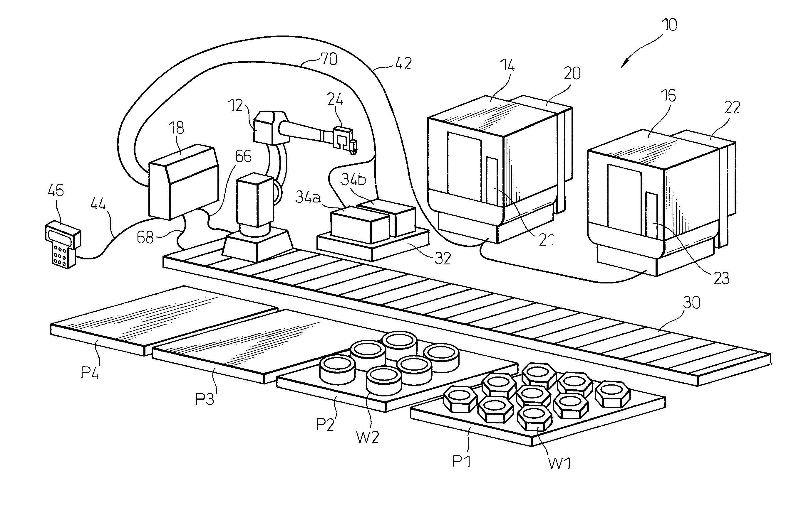
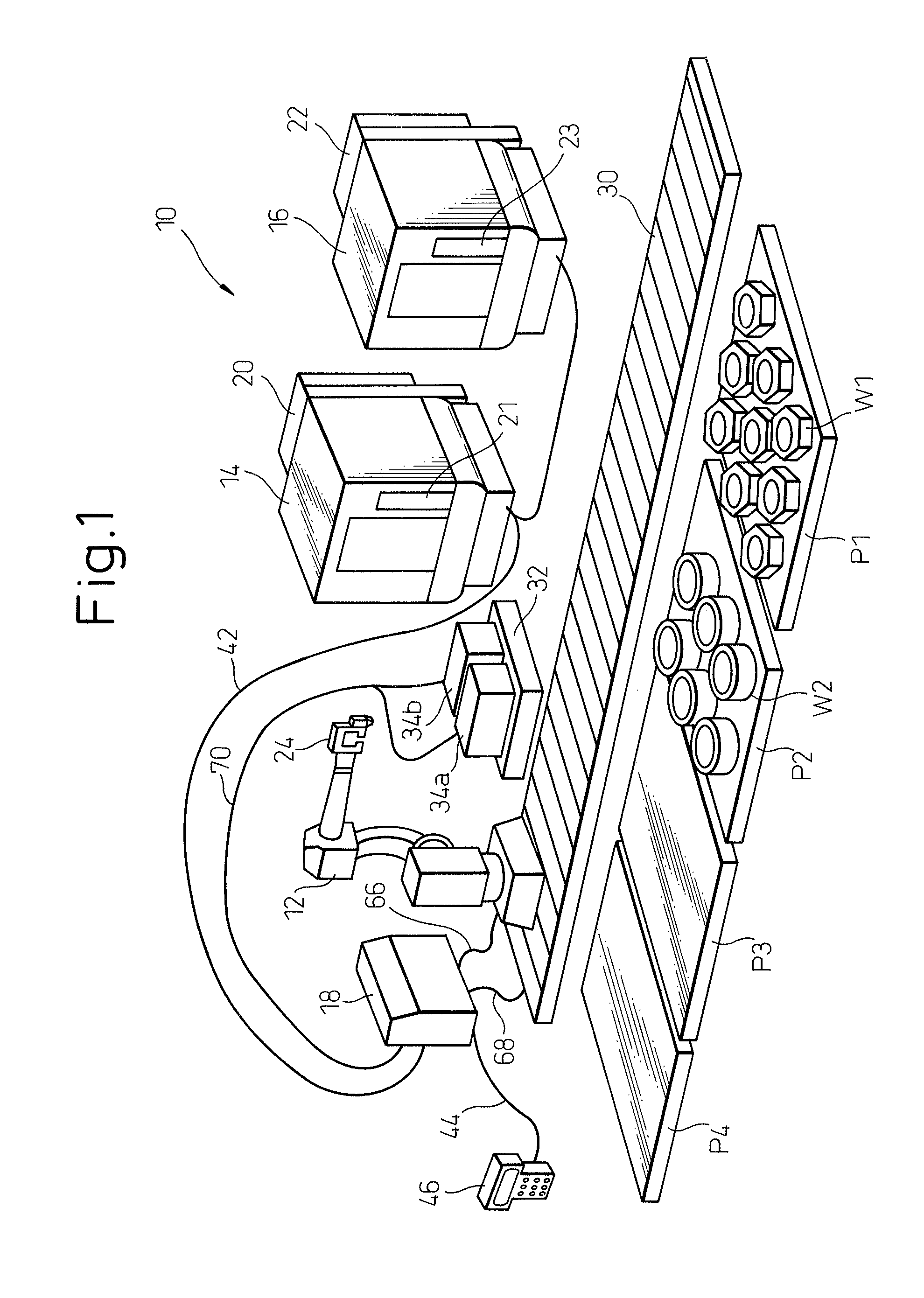
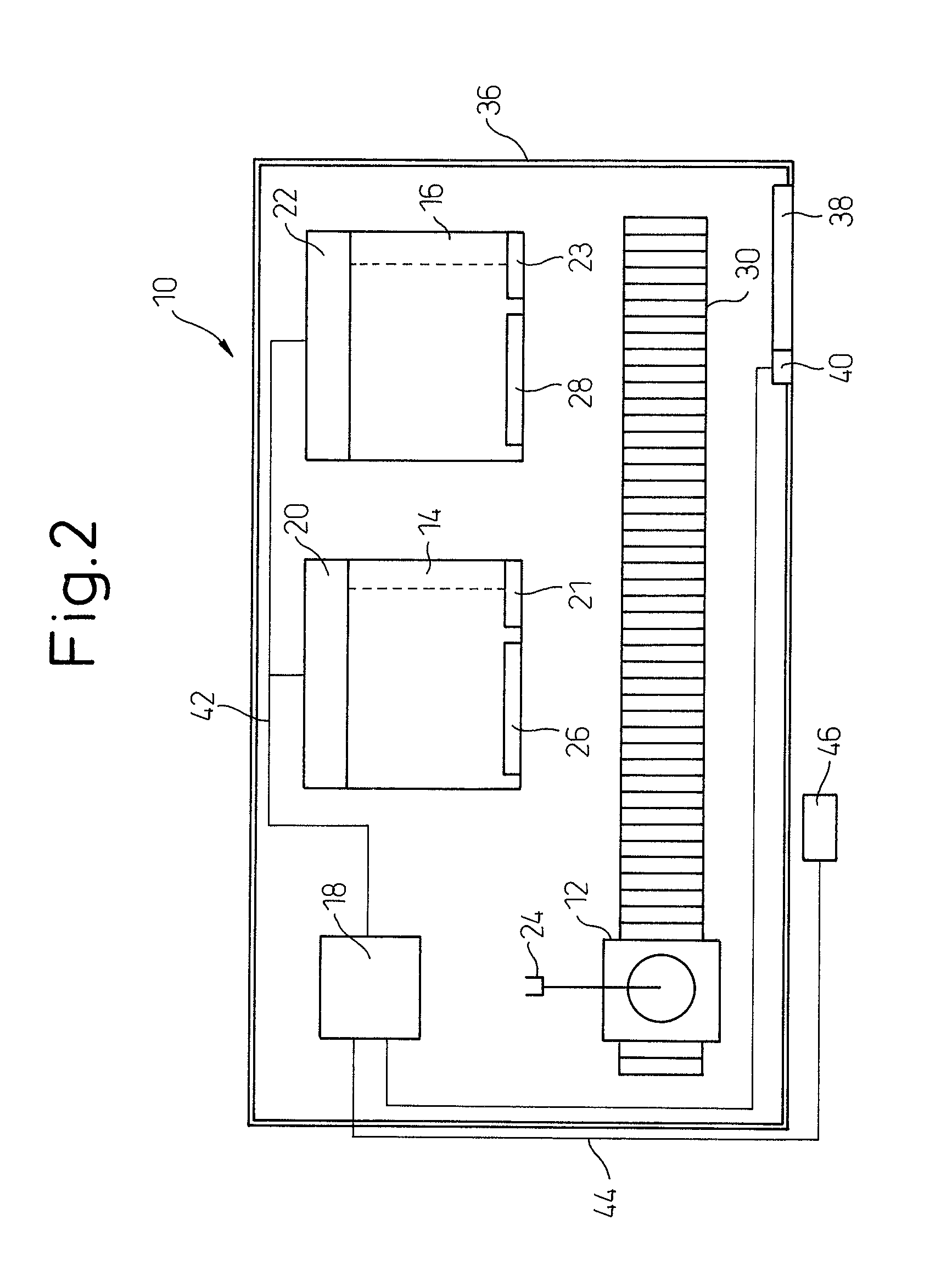
[0029]First, an overall configuration of a machining system 10, to which a robot control system according to one embodiment of the present invention is applied, will be described with reference to FIGS. 1 and 2.

[0030]Referring to FIGS. 1 and 2, a machining system 10 includes a robot 12; a plurality of machine tools 14 and 16; a robot controller 18 for controlling the robot 12; and machine tool controllers 20 and 22 for controlling respectively the machine tools 14 and 16. The mechanical configuration of the robot 12 may have any desired configuration so long as the robot can transfer a workpiece. In the embodiment depicted in FIG. 1, the robot 12 has a mechanical configuration of an articulated robot, and a working tool (or an end effector) 24 is attached to a wrist of the robo...


PUM


Abstract

A robot control system provided in a machining system including a robot and a machine tool. The robot control system includes a robot controller controlling the robot, a portable teach pendant connected to the robot controller, and a communication network adapted to connect the robot controller to a machine tool controller controlling the machine tool. The teach pendant includes a display section configured to display information relating to the robot and the machine tool. The robot controller includes a processing section configured to obtain information relating to the machine tool from the machine tool controller through the communication network, make the display section of the teach pendant display a machine tool-related screen in accordance with a given screen program, and make the machine tool-related screen of the display section of the teach pendant display the information, as obtained, relating to the machine tool.

Description

BACKGROUND OF THE INVENTION[0001]1. Field of the Invention[0002]The present invention relates to a robot control system provided in a machining system including a robot and a machine tool.[0003]2. Description of the Related Art[0004]In a machining using a machine tool, it is desired to make the machine tool operate for twenty-four consecutive hours in order to raise the operation rate of the machine tool. To this end, it is required that an operator performing operations for feeding an unprocessed workpiece to the machine tool (i.e., a loading operation) and removing a processed workpiece from the machine tool (i.e., an unloading operation) works for a long time. However, a machining job site where the machine tool is used may be in a hostile environment in which droplets of cutting oil used for a machining and chips produced in the machining are suspended. Further, in the operations for feeding and removing the workpiece, carrying a heavy workpiece by a manual-handling or using a c...

Claims


Application Information

Patent Timeline
IPC IPC(8): G05B15/00B25J9/22
CPCB23Q17/00G05B19/409Y02P90/18Y02P90/087G05B19/41825Y02P90/02
Inventor NISHI, HIROJIKATO, TETSUAKI
Owner FANUC LTD
Learn More