Borehole compensated resistivity logging tool having an asymmetric antenna spacing

a resistivity logging and antenna spacing technology, applied in seismology for water logging, instruments, detection using electromagnetic waves, etc., can solve the problems of increasing the length of the tool, increasing the tool length, and other sensors being located, so as to achieve accurate borehole compensation and reduce the overall tool length

Inactive Publication Date: 2010-12-02
SMITH INT INC
View PDF8 Cites 12 Cited by
  • Summary
  • Abstract
  • Description
  • Claims
  • Application Information

AI Technical Summary

Benefits of technology

[0010]Exemplary embodiments of the present invention advantageously provide several technical advantages. For example, exemplary embodiments of the invention advantageously provide for accurate borehole compensation whi

Problems solved by technology

While this approach is commercially viable, one drawback is that it results in a significantly increased tool length.
The increased tool length results in other sensors being located further from the bit.
Increased t

Method used


Image

  • Borehole compensated resistivity logging tool having an asymmetric antenna spacing
  • Borehole compensated resistivity logging tool having an asymmetric antenna spacing
  • Borehole compensated resistivity logging tool having an asymmetric antenna spacing

Examples


Embodiment Construction

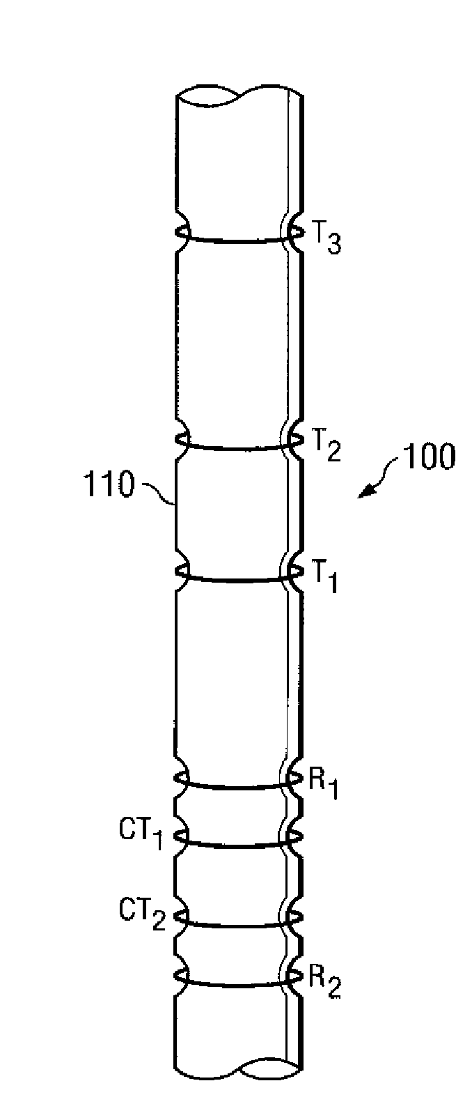
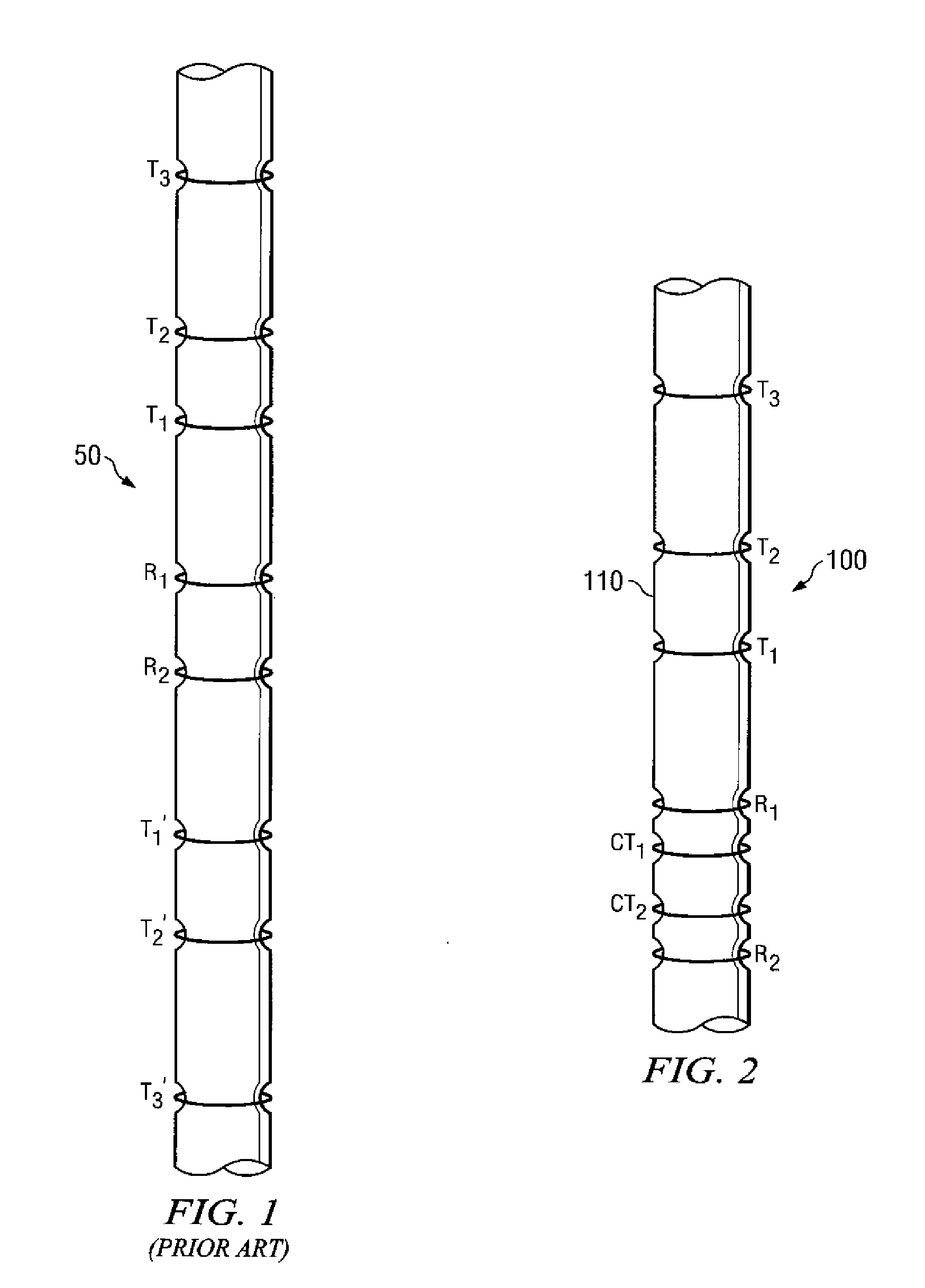
[0019]FIG. 2 depicts one exemplary embodiment of an LWD resistivity tool 100 in accordance with the present invention. Resistivity tool 100 includes a plurality of spaced transmitters T1, T2, and T3 and a pair of spaced receivers R1 and R2 deployed about a tool body 110. The transmitters T1, T2, and T3 may be thought of as being asymmetric in that they are deployed on one axial side of the receiver pair R1 and R2 and in that there are no corresponding symmetric transmitters deployed on the opposite axial side of the receivers. In contrast to the prior art resistivity tool 50 depicted on FIG. 1, the present invention does not include a second set of symmetric transmitters. Resistivity tool 100 further includes a pair of symmetric compensating transmitters CT1 and CT2. In the exemplary embodiment depicted on FIG. 2, these compensating transmitters CT1 and CT2 are deployed axially between the receiver pair R1 and R2. While the invention is not limited in this regard (the compensating t...


PUM


Abstract

A compensated resistivity logging while drilling tool having axially asymmetrically spaced transmitters is configured to provide compensated resistivity measurements. In one exemplary embodiment, the tool includes first and second compensating transmitters, preferably deployed axially symmetrically between first and second spaced receivers. The tool further includes a plurality of transmitters deployed axially asymmetrically with respect to the receivers, e.g., on one axial side of the receivers. The compensating transmitters are configured to acquire a borehole compensation that may be subtracted from conventional phase and attenuation measurements.

Description

RELATED APPLICATIONS[0001]None.FIELD OF THE INVENTION[0002]The present invention relates generally to downhole measurement tools utilized for measuring electromagnetic properties of a subterranean borehole. More particularly, the invention relates to borehole compensated resistivity logging tools having asymmetric transmitter spacing along the longitudinal axis of the tool.BACKGROUND OF THE INVENTION[0003]The use of electrical measurements in prior art downhole applications, such as logging while drilling (LWD), measurement while drilling (MWD), and wireline logging applications is well known. Such techniques may be utilized to determine a subterranean formation resistivity, which, along with formation porosity measurements, is often used to indicate the presence of hydrocarbons in the formation. For example, it is known in the art that porous formations having a high electrical resistivity often contain hydrocarbons, such as crude oil, while porous formations having a low electrica...

Claims


Application Information

Patent Timeline
IPC IPC(8): G01V3/30G06F19/00
CPCG01V3/30
Inventor LI, JING
Owner SMITH INT INC
Why Eureka
Try Eureka