
Method for retrofitting air plenum grommets

Active Publication Date: 2010-12-09
CUSTOM PLASTIC DISTIBUTORS
View PDF14 Cites 11 Cited by
  • Summary
  • Abstract
  • Description
  • Claims
  • Application Information

AI Technical Summary

Benefits of technology

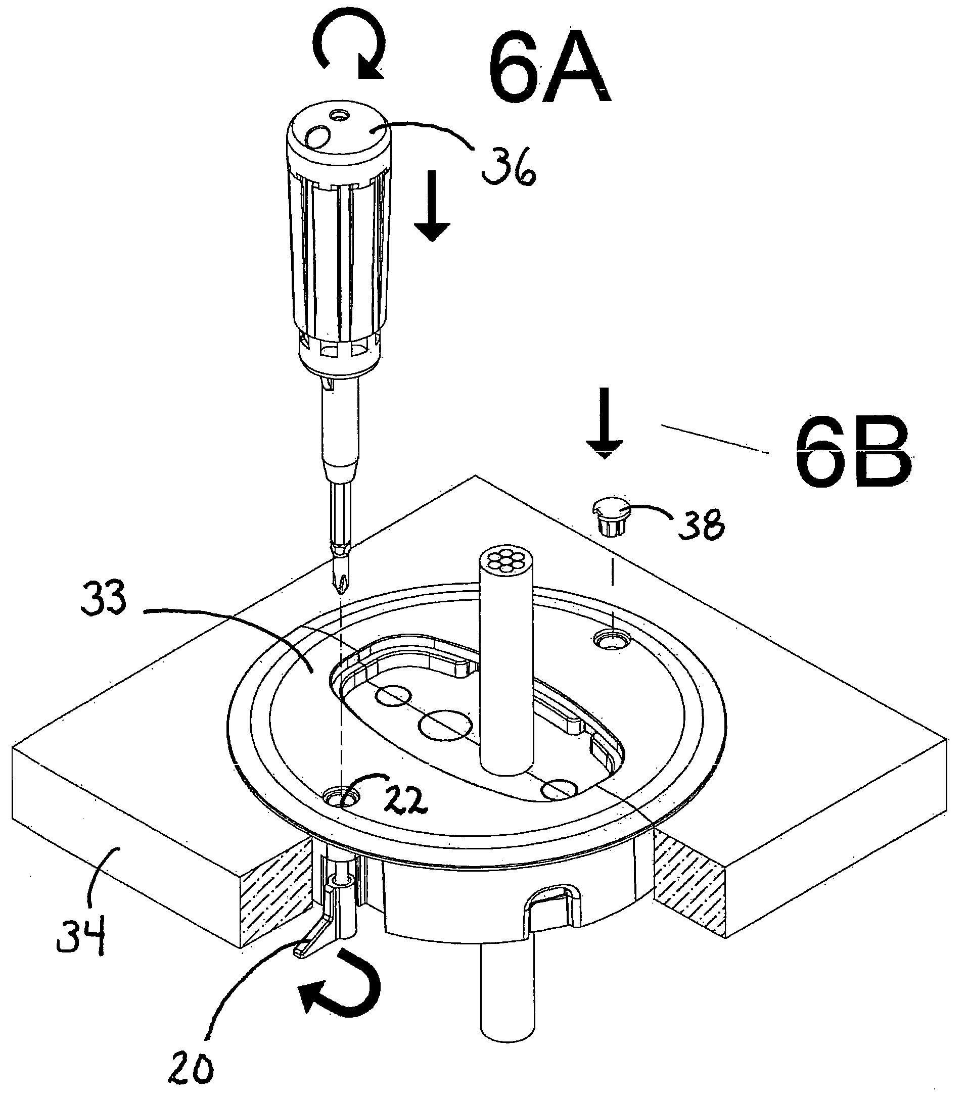
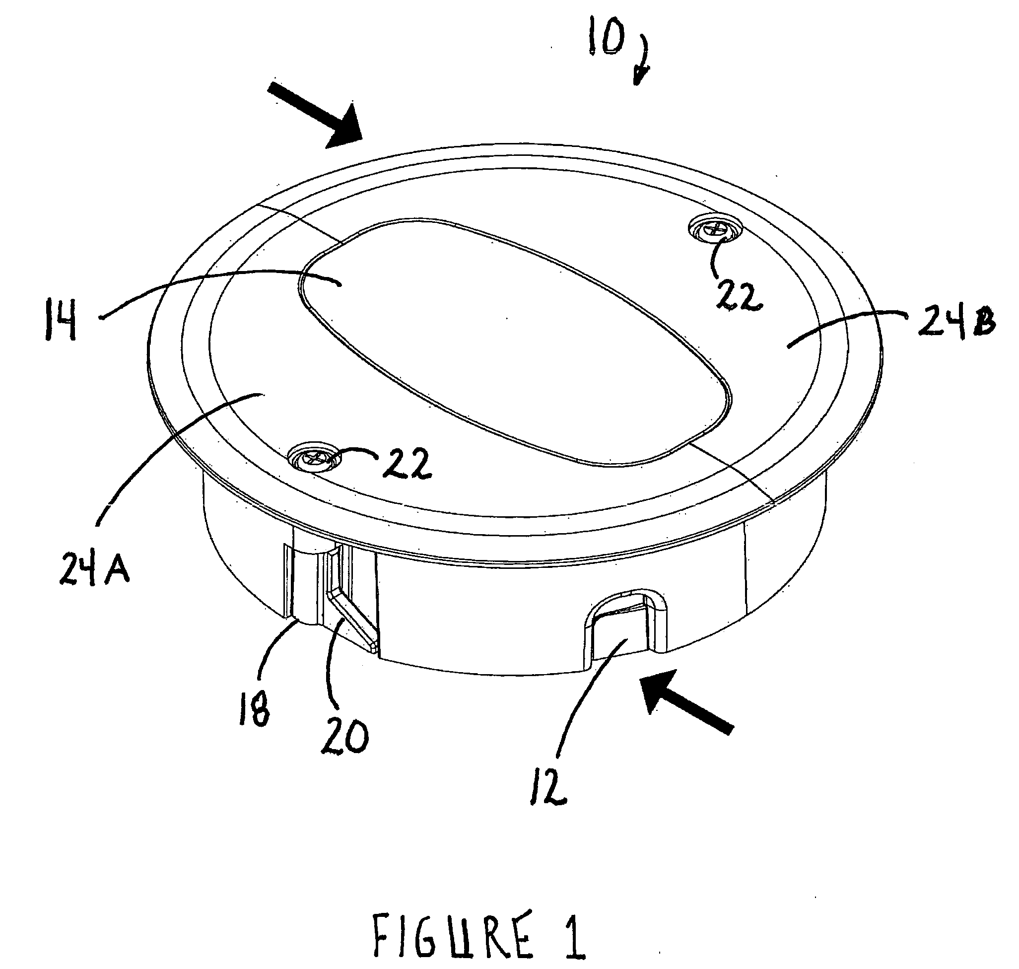
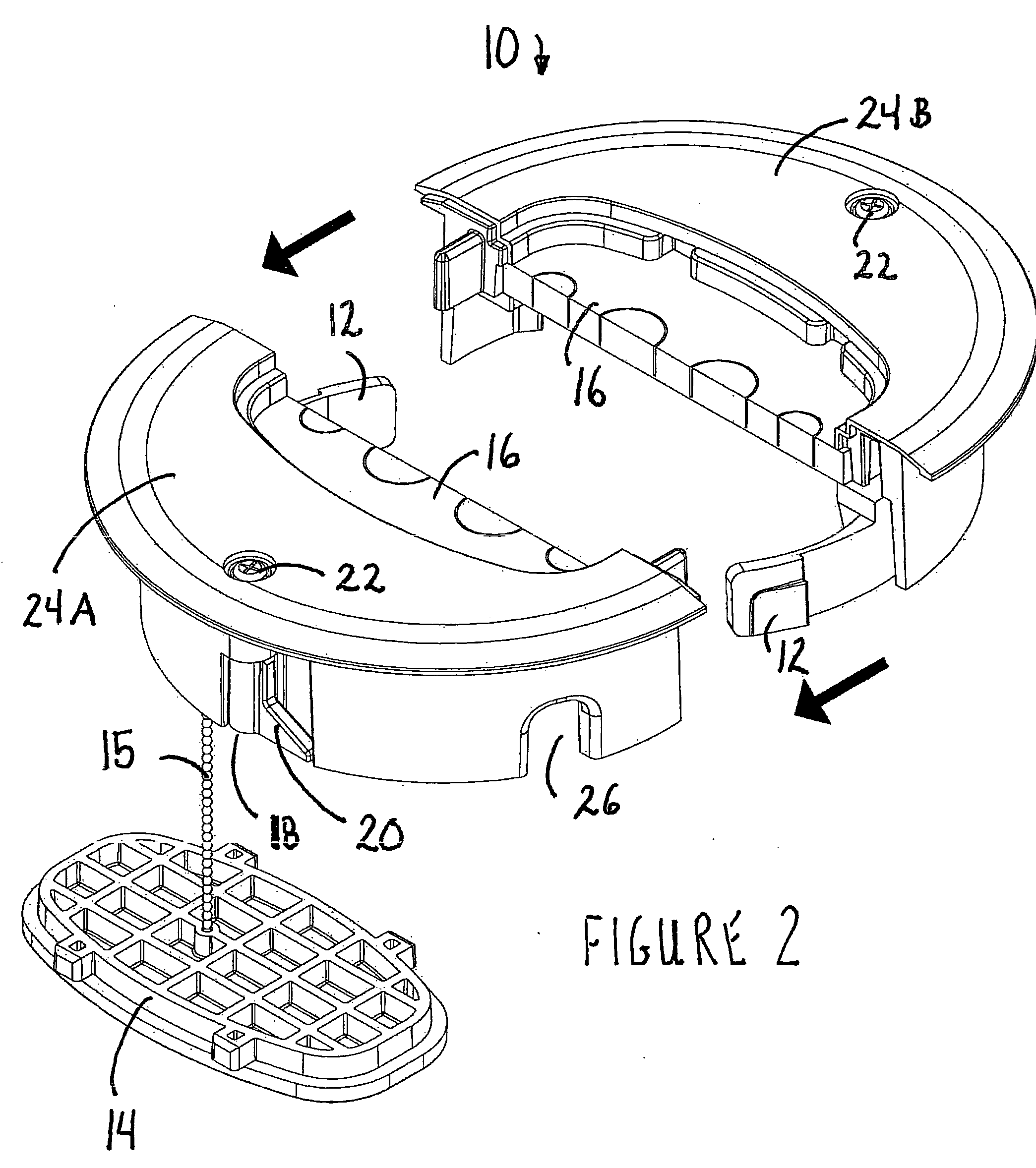
[0012]The present invention comprises a split gasket seal grommet that is positioned within an aperture in the access floor panel. The novel split gasket seal grommet removes the need for an outer housing ring and facilitates quick and easy installation of the grommet. A preferred embodiment of the present invention provides a flame-retardant gasket that defines a plurality of optional cable knockouts. The unit is designed as a high load performance grommet and the gasket provides an excellent air seal around cables. Moreover, a retained center cover forms a solid lid for the unit when no cables are passing through the grommet.
[0013]A grommet according to the present invention provides for: i) reduced air-loss and increased static pressure for underfloor air installations; (ii) improved cooling efficiencies and extended cooling equipment life; (iii) reduced cooling plant running costs; (iv) sealing of cable openings to prevent under-floor contamination; and (v) flexible floor panel cutout installation placement options. A preferred embodiment of the present invention is fabricated from a high strength flame retardant Acrylonitrile-Butadiene-Styrene (“ABS”) wherein the unit is inherently anti-static. In addition, the unit comprises a quick spring clamp design and includes corresponding body-matching cover plug inserts for aesthetic purposes.

Problems solved by technology

Such grommets prevent the passage of HVAC to locations where such leakage would be problematic; such as, for example, providing a flow of heated air proximate to a stack of network servers.
It does not address the need for minimizing the flow of HVAC through the grommet.
The prior art grommets described above and others known in the art do not provide for an economical and efficient method for retrofitting a raised flooring system grommet for cable and air flow management.

Method used


Image

  • Method for retrofitting air plenum grommets
  • Method for retrofitting air plenum grommets
  • Method for retrofitting air plenum grommets

Examples


Embodiment Construction

[0009]Specialized floor grommets are installed in the openings of raised flooring structures and are comprised of a cable-surrounding floor-sealing element. Typically, certain office building structures comprise raised flooring systems that define apertures for the passage of cables and wires therethrough. These cables typically comprise data and power cables for computer and telecommunications usage, and are found in special areas within the building structure. The present invention comprises a method and an apparatus designed for retrofitting cable management systems and repairing or replacing outdated cable management apparatus used in building platform technology where an access floor system is used to deliver a source of building air, such as HVAC, or simply the passage of the cables through a raised flooring structure.

[0010]Typically, HVAC is supplied under the raised floor and directed through air diffusers located throughout the raised flooring system. One of the problems en...


PUM


Abstract

A new and improved method is provided for repairing or retrofitting cable management apparatus used in raised flooring systems constructed to deliver a source of building air, or HVAC, while managing cables passing through an access port constructed in the raised flooring structure without jeopardizing the underfloor plenum air delivery systems. A raised floor grommet assembly provides a grommet locking mechanism defining an assembly retention system that lockingly engages and removeably disengages a first section and a second section of the grommet assembly, and an access port locking mechanism that lockingly engages and removeably disengages an access port constructed in the raised flooring structure. The unique grommet assembly provides an efficient and effective method and apparatus designed for retrofitting cable management systems and accommodates system upgrades, workstation relocation, and HVAC management.

Description

FIELD OF THE INVENTION[0001]The present invention relates to a new and improved method for retrofitting cable management systems and repairing or replacing outdated cable management apparatus used in building platform technology. A raised flooring system is typically constructed to deliver a source of building air such as heat, ventilation, and air conditioning (“HVAC”). In particular, the present invention comprises a method and an apparatus designed for managing, as a retrofit or repair operation, the cables passing through an access port constructed in the raised flooring structure without jeopardizing the underfloor plenum air delivery systems.BACKGROUND OF THE INVENTIONBrief Description of the Related Art[0002]With the continued development of information technology systems, there is a need to support a wide variety of workspaces designed for maximum connectivity flexibility. Connectivity locations often are required in highly visible office environments and must support, with ...

Claims


Application Information

Patent Timeline
IPC IPC(8): H02G3/22
CPCH02G3/085H02G3/185
Inventor ROY, DANIEL
Owner CUSTOM PLASTIC DISTIBUTORS
Learn More