Data transfer system, transmitting apparatus, receiving apparatus, radiographic image transfer system, and radiographic image diagnosis system

Inactive Publication Date: 2010-12-09
FUJIFILM CORP
View PDF6 Cites 1 Cited by
  • Summary
  • Abstract
  • Description
  • Claims
  • Application Information

AI Technical Summary

Benefits of technology

[0017]In the data transfer system according to the first aspect of the invention, a replacement table that is different from the correspondence table used for encoding is transferred. Therefore, when encoding is simply performed based on this replacement table, the data is not restored to a state before the encoding, so that even if an outsider receives a group of data, its contents would not be understood. If a person who knows that a replacement rule is correct inputs the correct replacement rule into the re-replacement table generating section, the data is restored to the state before the encoding. In other words, the replacement rule may be used as an encryption key. Furthermore, since the replacement table is generated by replacing a corresponding counterpart with another counterpart included in the correspondence for at least a part of the correspondence described in the correspondence table, processing for encryption is simple. Therefore, it is possible to avoid slowdown of processing necessary for transferring while protecting contents of data to be transferred.
[0078]As described above, according to the present invention, it is possible to realize the data transfer system, the transmitting apparatus, the receiving apparatus, the radiographic image transfer system, and the radiographic image diagnosis system capable of avoiding slowdown of processing while protecting contents of data to be transferred.

Problems solved by technology

Therefore, when encoding is simply performed based on this replacement table, the data is not restored to a state before the encoding, so that even if an outsider receives a group of data, its contents would not be understood.

Method used


Image

  • Data transfer system, transmitting apparatus, receiving apparatus, radiographic image transfer system, and radiographic image diagnosis system
  • Data transfer system, transmitting apparatus, receiving apparatus, radiographic image transfer system, and radiographic image diagnosis system
  • Data transfer system, transmitting apparatus, receiving apparatus, radiographic image transfer system, and radiographic image diagnosis system

Examples


second embodiment

[0255]FIG. 21 is a diagram illustrating a structure of a frame generated by a frame integration section in the second embodiment and an example of a replacement table.

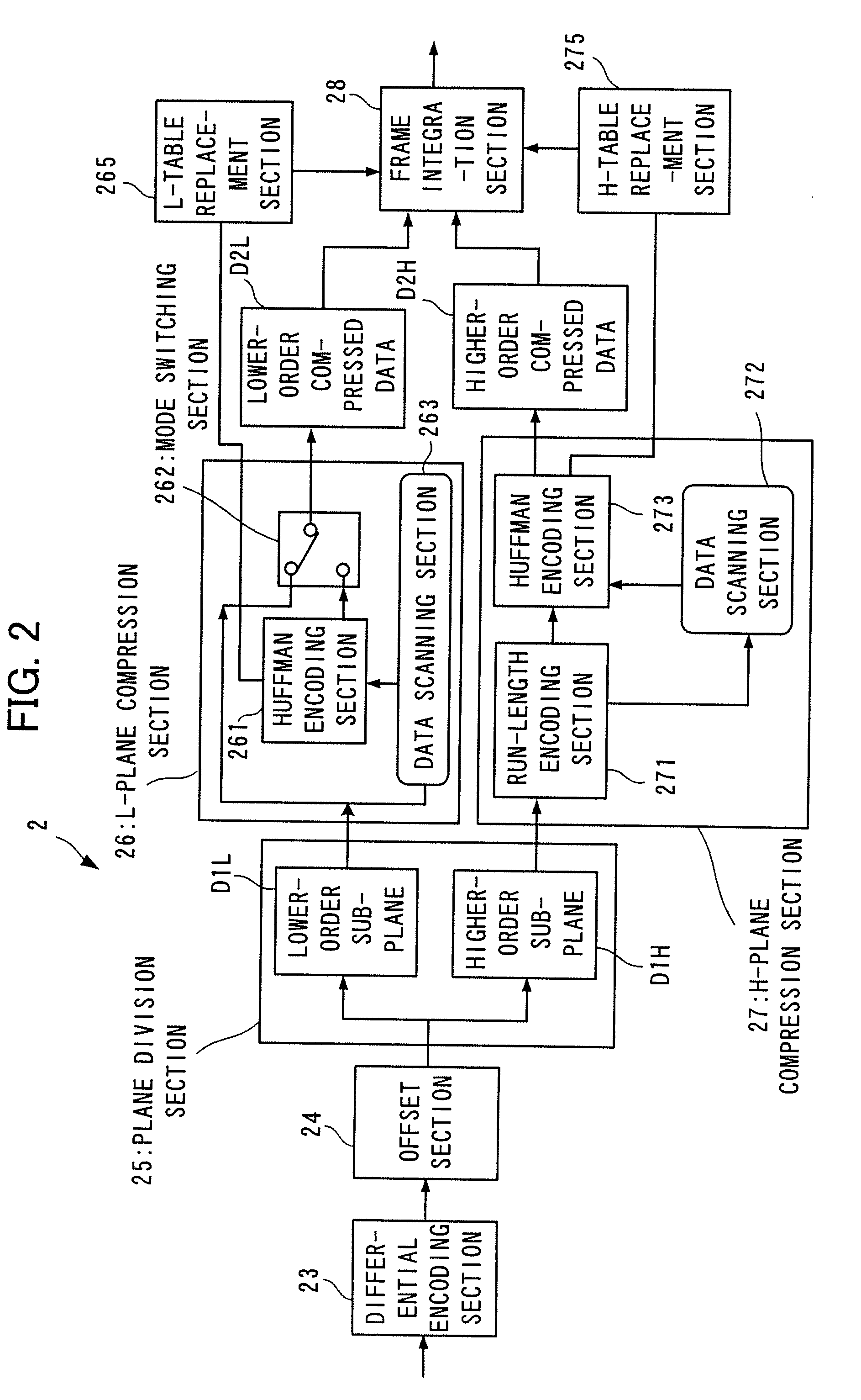
[0256]In the second embodiment, the H-table replacement section performs the replacement of numeric values also for the correspondence from the 1st to the 5th, in addition to the correspondence from the 6th to the 256th in the correspondence of the Huffman table. To be more specific, as illustrated in FIG. 17, the alignment of the 251 pieces of numeric values in the correspondence from the 6th to the 256th in the Huffman table is replaced in a reverse order, and furthermore, the alignment of numeric values in the correspondence from the 1st to the 5th in the Huffman table is replaced in a reverse order. In this way, the replacement is performed for most of the correspondence. This replacement is also the same for the L-table replacement section.

[0257]FIG. 22 is a diagram illustrating replacement rules stored in externa...

third embodiment

[0268]FIG. 24 is a diagram illustrating a compression processing section in the

[0269]A compression processing section 2000 in FIG. 24 is a section to compress image data by using an irreversible compression and a data compression is performed at a high compression ratio.

[0270]The compression processing section 2000 includes a thinning processing section 2505 to thin out TRUE pixels to be targeted to the reversible compression processing from all pixels making up an image represented by an image data, and as each section to perform an irreversible compression processing for FAKE pixels remaining after the TRUE pixels are thinned and to target for the irreversible compression processing, a FAKE-pixel-data compression section 2560 and an edge detection section 2525 are provided. Furthermore, in the compression processing section 2000, as each section to perform the reversible compression processing for the TRUE pixels, a second differential encoding section 2510, a second offset sectio...

fourth embodiment

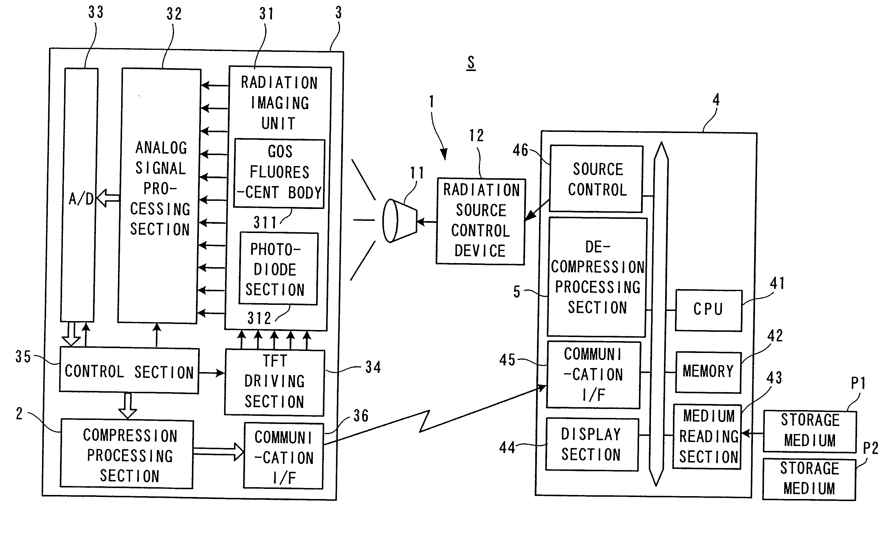
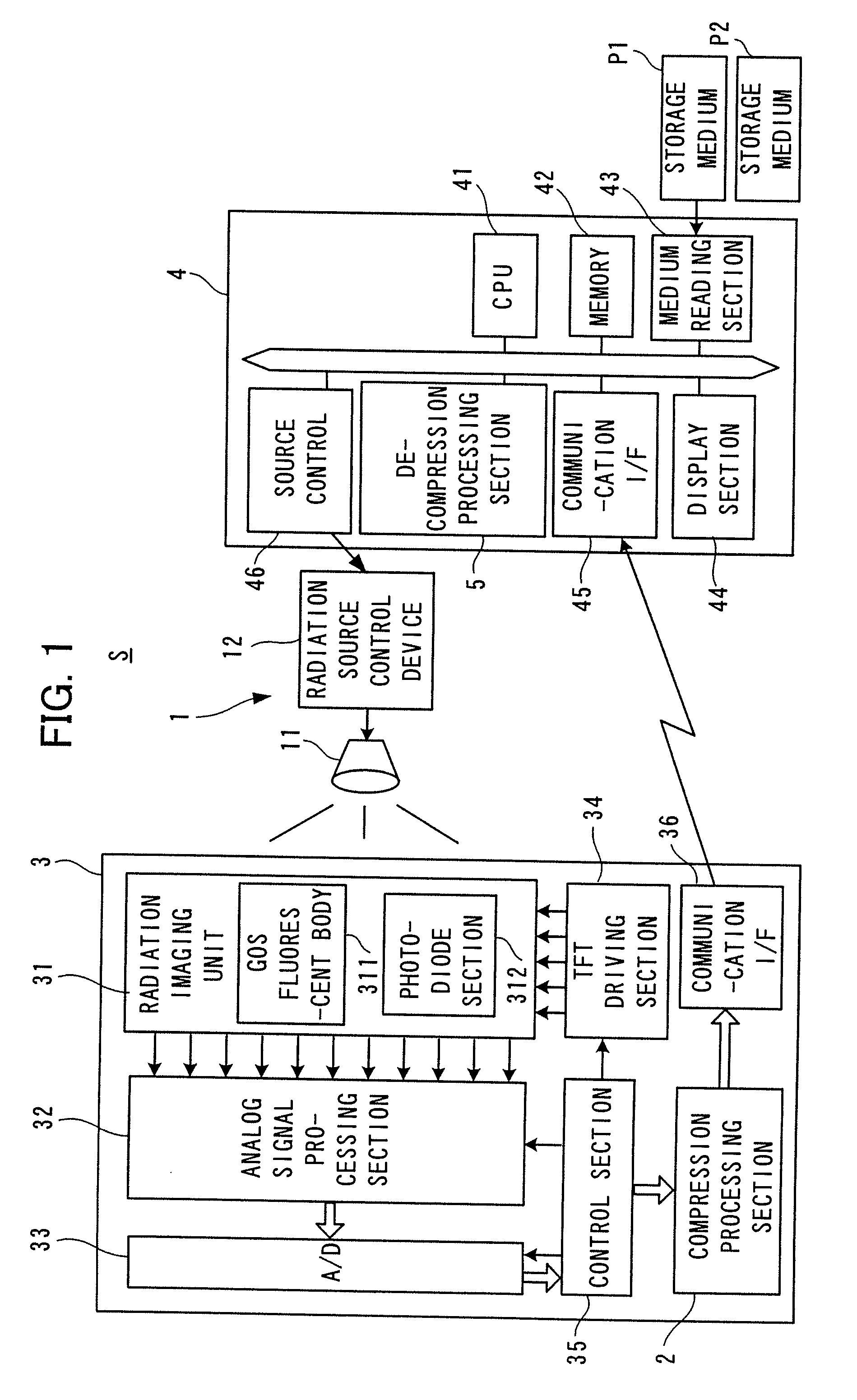
[0293]FIG. 27 is a block diagram illustrating a medical image transfer system via a network, which is a fourth embodiment according to the invention.

[0294]A medical image transfer system S2 in FIG. 27 includes a first system 6 provided in a first hospital and a second system 7 provided in a second hospital at a distant location from the first hospital 1.

[0295]The first system 6 includes an image server 61, a partial decoding section 62, a first display terminal 63, a complete decoding section 64, and a second display terminal 65.

[0296]The image server 61 incorporates a not-illustrated compression processing section similar to the compression processing section 2 in FIG. 1, and stores an radiographic image after applying compression processing to the radiographic image. That is, the image data stored in the image server 61 is already subjected to the encoding processing explained with reference to FIG. 2 through FIG. 21, and includes a replacement table in which a part of the Huffman...


PUM


Abstract

A data transfer system capable of avoiding slowdown of processing while protecting contents of data to be transmitted is provided. The data transfer system includes a transmitting apparatus that transmits data and a receiving apparatus that receives the transmitted data. The transmitting apparatus includes: an encoding section supplied with to-be-converted data, converts the data into a code by using a correspondence table in which one-to-one correspondence between data values and codes is described and generates encoded data; a replacement table generating section that, for at least a part of the correspondence described in the correspondence table used by the encoding section, replaces a corresponding counterpart with another counterpart included in the correspondence, and generates a replacement table; and a transmitting section that transmits a group of data in which the encoded data generated by the encoding section and the replacement table generated by the replacement table generating section are combined.

Description

TECHNICAL FIELD [0001]The present invention relates to a data transfer system, a transmitting apparatus, a receiving apparatus, a radiographic image transfer system, and a radiographic image diagnosis system.BACKGROUND ART [0002]A data transfer system that encodes data and transmits the data from a transmitting apparatus and receives the data by a receiving apparatus and decodes and utilizes the data is employed in various types of apparatuses.[0003]For example, in a radiographic image diagnosis system used for diagnosis of disease, a subject as a target for diagnosis is subjected to radiation from a radiation source, and the radiation after passing through the subject is emitted to a fluorescent body in a detection panel unit. In the detection panel unit, an image generated by the light emission of the fluorescent body is electrically read, so that image data of the subject after passing through radiation is obtained. The image data is transferred from the detection panel unit to a...

Claims


Application Information

Patent Timeline
IPC IPC(8): G06K9/62G06F13/12
CPCH04N19/13H04N19/593H04N19/103H04N19/91H04N19/69H04N19/182H04N19/167H04N19/93H04N19/34H04N19/14H04N21/2347
Inventor SUGITA, YUKIO
Owner FUJIFILM CORP
Why Eureka
Try Eureka