Device for extruding a thermoplastic plastic product

a technology of thermoplastic material and extruder, which is applied in the direction of applications, manufacturing tools, sweetmeats, etc., can solve the problems of increasing the driving power of the apparatus, increasing the wear and tear of the apparatus, and not being able to ensure an even quality of the degassed and cleaned plastic material, so as to reduce wear and tear, improve the degasification performance, and be produced easily separately

Active Publication Date: 2010-12-09
EREMA ENG RECYCLING MASCH & ANLAGEN GMBH
View PDF12 Cites 5 Cited by
  • Summary
  • Abstract
  • Description
  • Claims
  • Application Information

AI Technical Summary

Benefits of technology

[0011]In addition or as an alternative to this, the extruder screw can be arranged in at least three parts in the longitudinal direction of the screw, with the individual parts, which are the part of the plasticizing section, the part of the screw section with the flow arrester and the partial section comprising the degasification section and the outlet section, being preferably screwed together along the screw axis. The individual screw sections can thus easily be produced separately and can then be screwed together following preliminary mounting of the sleeve on the screw section forming the flow arrester, thus enabling a combination of a large variety of screw geometries among other things. Moreover, a return-feed thread plus sleeve which will wear off more quickly can be exchanged without having to newly produce the entire extruder screw.
[0012]In order to improve the degasification performance, the extruder worm can form a counter-rotating delivery flight in the known manner between the counter-rotating delivery flight and the opening of the flow channel on the outlet side, with the housing preferably comprising at least one degasification opening in the transitional region between the counter-rotating and the concurrent delivery flight. In order to reduce wear and tear of the delivery flight downstream of the plasticizing section as a result of contaminated gases penetrating the delivery flight, it is advantageous when the flow channel on the outlet side of the melt filter is connected by at least one return channel, preferably via a non-return valve, with the counter-rotating delivery flight of the extruder screw on the inlet side. A purposeful low return flow of cleaned plastic can be ensured through the delivery flight to the plasticizing section and thus the penetration of contaminated plastic into the counter-rotating delivery flight can be prevented.
[0013]In order to improve the degasification effect, a ductless degasification space can be provided in the sleeve between the counter-rotating and concurrent delivery flight of the extruder screw, which space is formed by the extruder screw and / or the sleeve. Gases which penetrate this region via the counter-rotating and concurrent delivery flight are simply discharged from the apparatus via the degasification opening, through which the desired pressure decoupling is ensured and a transfer of contaminated gases is securely prevented.

Problems solved by technology

The disadvantage of this apparatus is especially that the counter-rotating feeding thread concerns a dynamic seal which is tight or not depending on the speed of the extruder screw.
These vapors are the carriers of dirt particles, among other things, which are introduced past the filter into the degasification section and contaminate the already filtered plastic again, so that it is not possible to ensure an even quality of the degassed and cleaned plastic material.
The aforementioned apparatus comes with the disadvantage however that the flow arrester with a screw section having a counter-rotating delivery flight leads to a considerably increased driving power for the apparatus and also increased wear and tear of the apparatus.

Method used


Image

  • Device for extruding a thermoplastic plastic product
  • Device for extruding a thermoplastic plastic product
  • Device for extruding a thermoplastic plastic product

Examples


Embodiment Construction

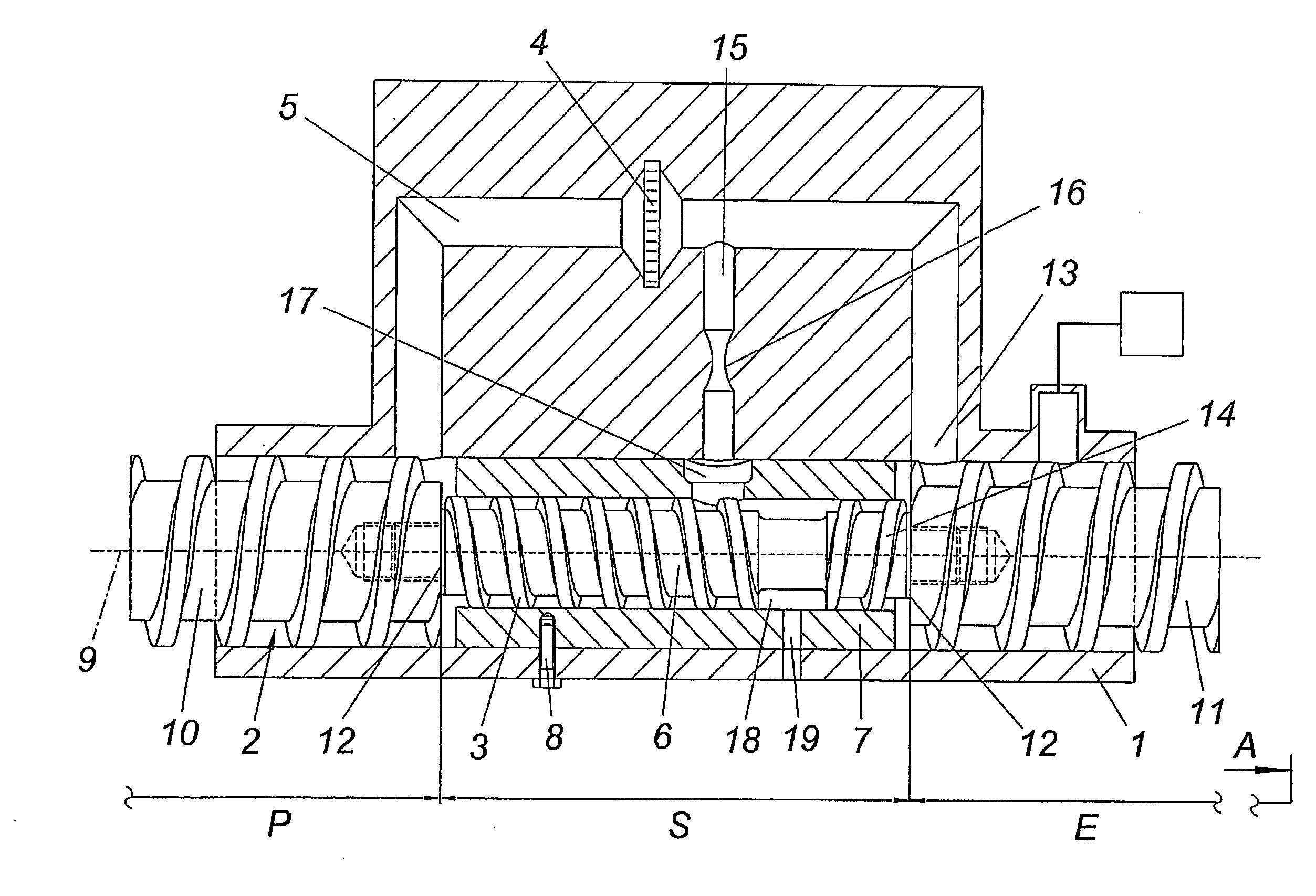
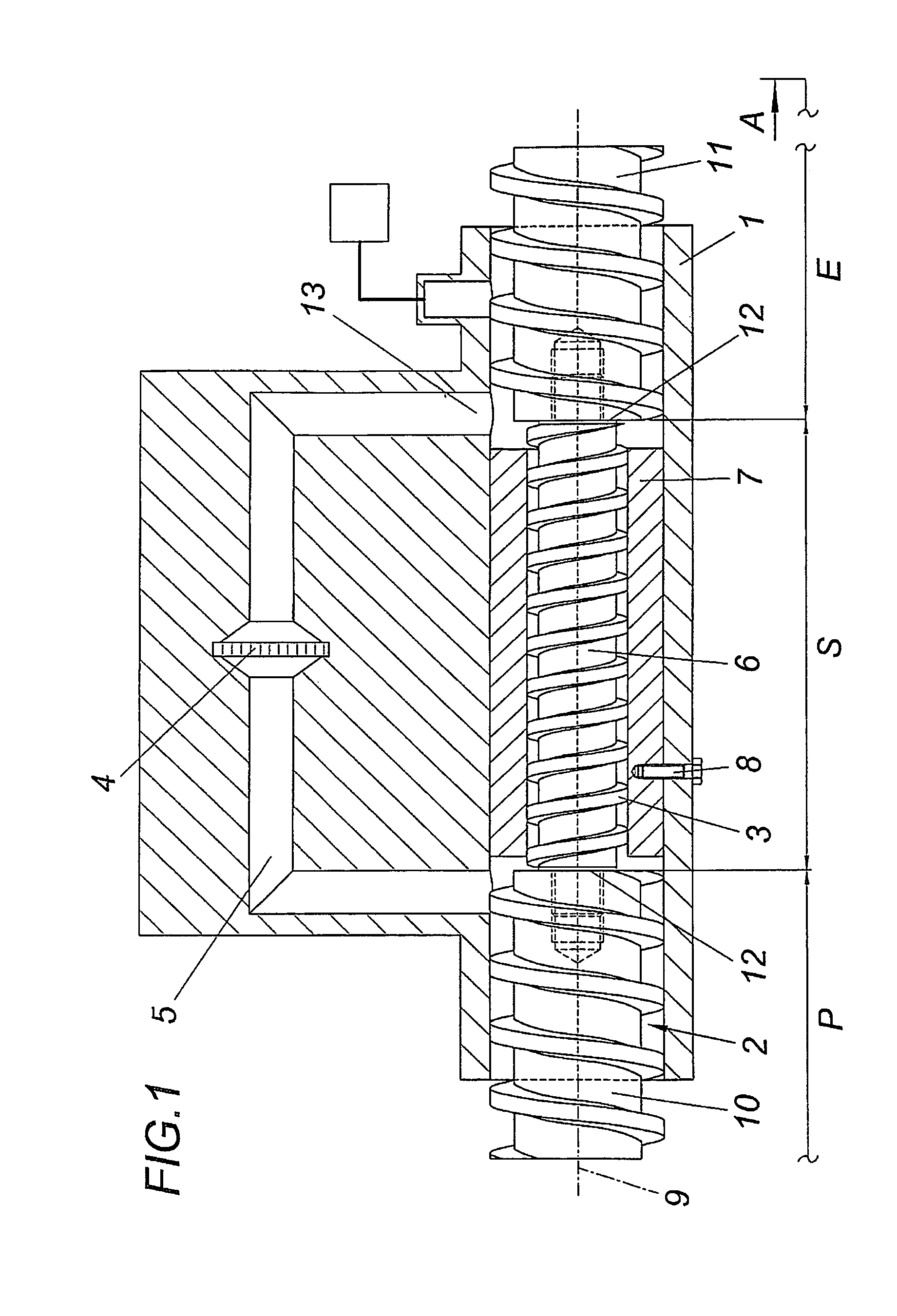
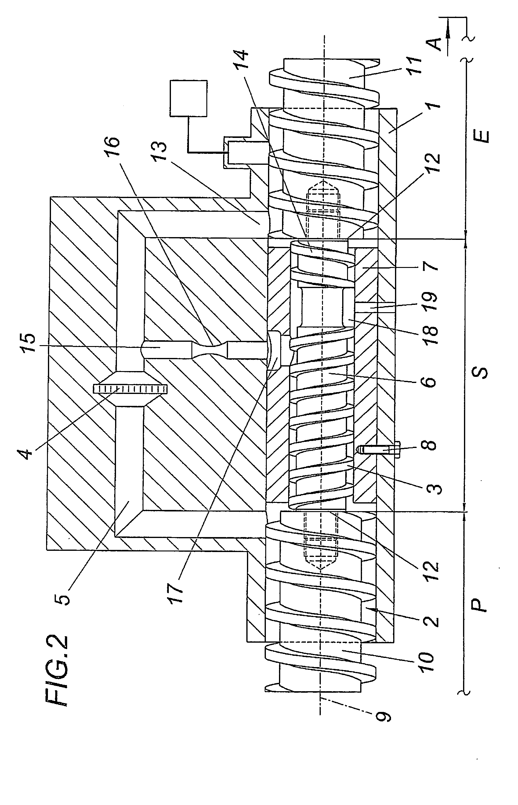
[0017]An apparatus for extruding thermoplastic material comprises an extruder screw 2 held in a housing 1, which screw comprises a plasticizing section P on the inlet side and a degasification section E upstream of an indicated outlet section A. A screw section forming a flow arrester S with a screw section with counter-rotating delivery flight 3 being provided between the plasticizing section P and the degasification section E. Furthermore, housing 1 comprises at least one flow channel 5 which bridges the flow arrester S and contains a melt filter 4. In order to reduce the driving power and the wear and tear of the extruder screw 2, the screw section forming the flow arrester S is associated with a sleeve 7 which is held in the housing 1 in a torsion-proof manner and comprises the screw 6, and the screw 6 in the screw section of the flow arrester S has a smaller screw diameter in relation to the plasticizing section P and the degasification section E. The twist protection of the sl...


PUM

PropertyMeasurementUnit
diameteraaaaaaaaaa
speedaaaaaaaaaa
viscosityaaaaaaaaaa

Abstract

The invention relates to an apparatus for extruding thermoplastic material, comprising an extruder screw (2) which is mounted in a housing (1), comprises a plasticizing section (P) on the inlet side, a degasification section (E) upstream of an outlet section (A), a flow arrester (S) between the plasticizing section (P) and the degasification section (E) with a screw section with a counter-rotating delivery flight (3), and at least one flow channel (5) bridging the flow arrester (S) and containing a melt filter (4). In order to reduce the driving power of the extruder screw (2) it is proposed that a sleeve (7), which encompasses the screw (6) and is mounted in the housing (1) in a rotationally fixed manner, is associated with the screw section that forms the flow arrester (S), and the screw (6) in the screw section of the flow arrester (S) has a smaller screw diameter in relation to the plasticizing section (P) and preferably also to the degasification section (E).

Description

1. FIELD OF THE INVENTION[0001]The invention relates to an apparatus for extruding thermoplastic material, comprising an extruder screw which is mounted in a housing, comprises a plasticizing section on the inlet side, a degasification section upstream of an outlet section, a flow arrester between the plasticizing section and the degasification section with a screw section with a counter-rotating delivery flight, and with at least one flow channel bridging the flow arrester and containing a melt filter.2. DESCRIPTION OF THE PRIOR ART[0002]Such apparatuses are used for appropriately degassing and preparing plastic materials, especially plastic waste, which require a degasification and cleaning process prior to further processing. In the treatment of plastic materials from production waste or from the plastic material that has already been in circulation, the necessity arises that these plastic materials are treated prior to re-use as a result of labeling, lacquering or soiling.[0003]...

Claims


Application Information

Patent Timeline
Patent Type & Authority Applications(United States)
IPC IPC(8): B29C47/38B29C48/03B29C48/38B29C48/395B29C48/455B29C48/55B29C48/69B29C48/693B29C48/74B29C48/76
CPCB29C47/0009B29C47/0871B29C47/38B29C47/6037B29C47/50B29C47/686B29C47/745B29C47/767B29C47/46B29C47/68B29C48/03B29C48/268B29C48/395B29C48/455B29C48/38B29C48/55B29C48/69B29C48/693B29C48/745B29C48/767B29B7/845B29B7/58B29B7/429
Inventor SCHULZ, HELMUTH
Owner EREMA ENG RECYCLING MASCH & ANLAGEN GMBH
Why Eureka
Try Eureka