Method and System for a Low Noise Amplifier Utilizing a Leaky Wave Antenna

a leaky wave antenna and amplifier technology, applied in the field of low noise amplifiers utilizing leaky wave antennas, can solve the problems of power inefficiency of transmitters and/or receivers in comparison to other blocks of portable communication devices

Inactive Publication Date: 2010-12-09
AVAGO TECH INT SALES PTE LTD
View PDF36 Cites 42 Cited by
  • Summary
  • Abstract
  • Description
  • Claims
  • Application Information

AI Technical Summary

Benefits of technology

[0018]FIG. 7 is a block diagram of low-noise amplifiers utilizing a leaky wave antenna, in accordance with an embodiment of the invention.
[0019]FIG. 8 is a block diagram illustrating exemplary steps for low noise amplifiers utilizing a leaky wave antenna, in accordance with an embodiment of the invention.

Problems solved by technology

Additionally, transmit and / or receive circuitry within such mobile wireless devices often account for a significant portion of the power consumed within these devices.
Moreover, in some conventional communication systems, transmitters and / or receivers are often power inefficient in comparison to other blocks of the portable communication devices.

Method used


Image

  • Method and System for a Low Noise Amplifier Utilizing a Leaky Wave Antenna
  • Method and System for a Low Noise Amplifier Utilizing a Leaky Wave Antenna
  • Method and System for a Low Noise Amplifier Utilizing a Leaky Wave Antenna

Examples


Embodiment Construction

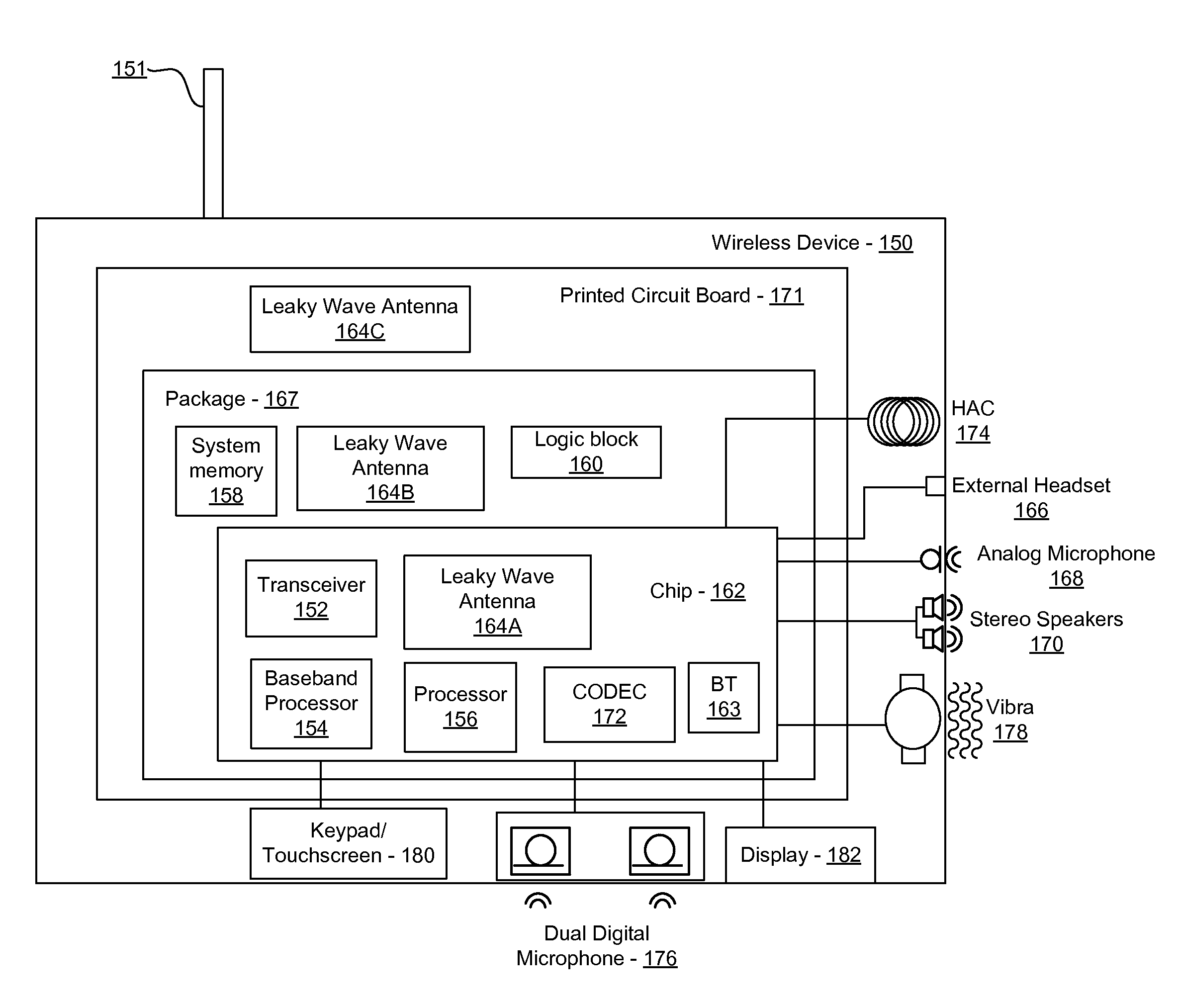
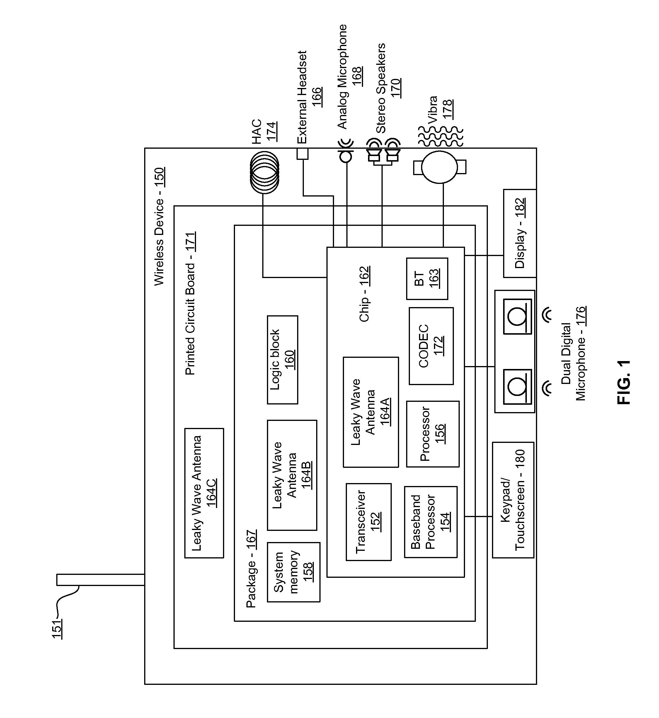
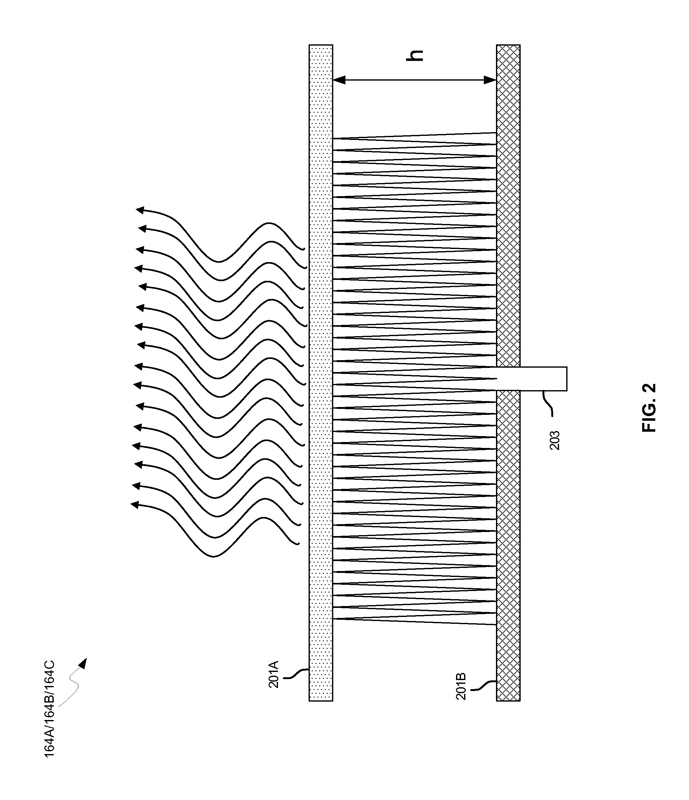
[0020]Certain aspects of the invention may be found in a method and system for a low noise amplifier utilizing a leaky wave antenna. Exemplary aspects of the invention may comprise one or more low-noise amplifiers coupled to one or more leaky wave antennas in a wireless device. RF signals may be received via one or more low-noise amplifiers coupled to one or more feed points on a leaky wave antenna. The one or more low-noise amplifiers may be coupled to the one or more feed points, based on an impedance of the one or more feed points on the leaky wave antenna and an input impedance of the one or more low-noise amplifiers. The impedance of the one or more feed points may be dependent on a location of the one or more feed points along a vertical axis in a resonant cavity of the leaky wave antenna. A height of the resonant cavity may be one half of a wavelength of the RF signals received by the leaky wave antenna. The vertical axis of the resonant cavity may run from a first reflective...


PUM


Abstract

Methods and systems for a low noise amplifier utilizing a leaky wave antenna are disclosed and may include one or more low-noise amplifiers (LNAs) coupled to one or more leaky wave antennas (LWAs) in a wireless device. RF signals may be received via one or more LNAs coupled to one or more feed points on a LWA. The one or more LNAs may be coupled to the feed points based on an impedance of the feed points and an input impedance of the one or more LNAs. The impedance of the feed points may be configured by locating them along a vertical axis in a resonant cavity of the LWA. The LWAs may be integrated on a chip, and/or on a package or printed circuit board to which the chip is affixed. The RF signals may be amplified by the LNAs and may be down-converted to baseband signals.

Description

CROSS-REFERENCE TO RELATED APPLICATIONS / INCORPORATION BY REFERENCE[0001]This application makes reference to, claims the benefit from, and claims priority to U.S. Provisional Application Ser. No. 61 / 246,618 filed on Sep. 29, 2009, and U.S. Provisional Application Ser. No. 61 / 185,245 filed on Jun. 9, 2009.[0002]This application also makes reference to:U.S. patent application Ser. No. ______ (Attorney Docket No. 21181US02) filed on even date herewith;U.S. patent application Ser. No. ______ (Attorney Docket No. 21205US02) filed on even date herewith;U.S. patent application Ser. No. ______ (Attorney Docket No. 21211US02) filed on even date herewith;U.S. patent application Ser. No. ______ (Attorney Docket No. 21227US02) filed on even date herewith;U.S. patent application Ser. No. ______ (Attorney Docket No. 21230US02) filed on even date herewith;U.S. patent application Ser. No. ______ (Attorney Docket No. 21231US02) filed on even date herewith;U.S. patent application Ser. No. ______ (Atto...

Claims


Application Information

Patent Timeline
Patent Type & Authority Applications(United States)
IPC IPC(8): H04B7/00
CPCH01Q1/2283H01Q13/22H04B5/0031H01Q15/006G01S13/06H01Q13/20H04B1/04H04B7/24H04B1/0458H01L2224/16225H01L2224/32225H01L2224/73204H01L2924/13091H01L2924/00G06K7/10316H01Q15/0066H01Q15/23H01Q19/06
Inventor ROFOUGARAN, AHMADREZAROFOUGARAN, MARYAM
Owner AVAGO TECH INT SALES PTE LTD
Why Eureka
Try Eureka