Surgical retractor

a retractor and surgical technology, applied in the field of expandable retractors, can solve the problems of prolonging the retraction time of tissues, affecting the operation efficiency of surgeons, and significant trauma to the intervening tissues, and achieve the effect of greater visualization

Inactive Publication Date: 2010-12-09
DALTON BRIAN E
View PDF9 Cites 37 Cited by
  • Summary
  • Abstract
  • Description
  • Claims
  • Application Information

AI Technical Summary

Benefits of technology

[0008]Each of the pivotal segments is provided with an inwardly projecting contact protrusion for engaging the bottom advancing end of the collet for pivoting the segments on their axis. Respective protrusions may be removed for blades that are not to be pivoted. The collet is threadably engaged with the base frame to thereby threadably advance the collet downward by turning it clockwise relative to the frame.
[0009]The horizontal extending retractor blade handles engage the downwardly extending retractor blades through an angular handle section. These beveled portions of the handles allow greater visualization when the retractor blades are pivoted down and thereby outwardly, as otherwise the retractor blade handles, where they connect to the upper or posterior portions of the retractor blades, tend to protrude medially and obscure the view unless this bevel is in place.

Problems solved by technology

Traditional open surgical procedures performed on locations deep within the body can cause significant trauma to the intervening tissues.
Such procedures often require a long incision, extensive muscle stripping, prolong retraction of tissues, denervation and devascularication of tissue.
These traditional open surgeries can require extensive operating time and extensive post-operative recovery time, and in some cases, can lead to permanent scarring and more severe pain to the patient.
However, a deficiency incurred is that when the blades are pivoted or tilted, they must be done so independently which is not easy or always functional under operating conditions.
In addition, the selective removal or addition of surgical blades to and from the assembly is not readily or easily accomplished.

Method used


Image

  • Surgical retractor
  • Surgical retractor
  • Surgical retractor

Examples


Embodiment Construction

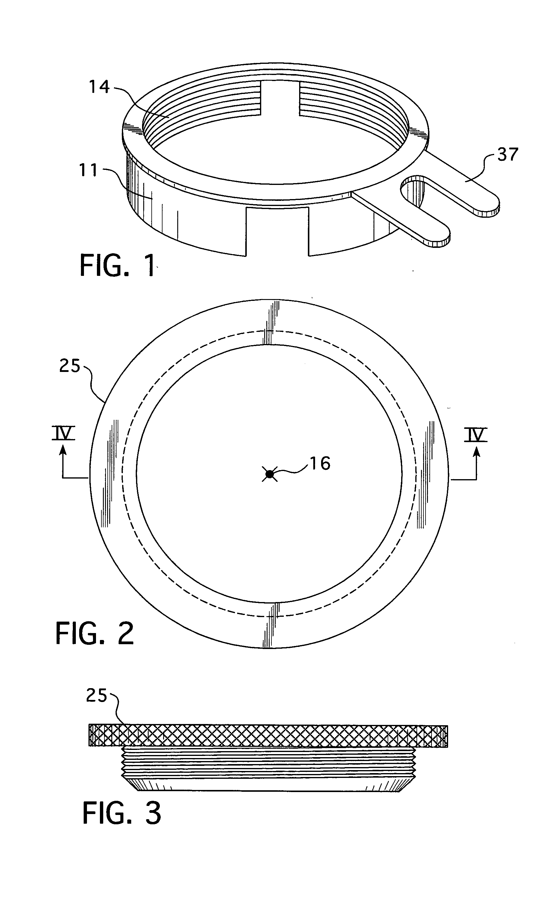
[0029]Referring first to the first embodiment of the present invention, reference is made to FIGS. 1 through 15.

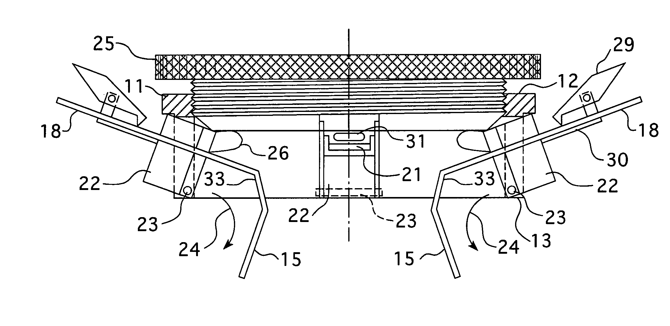
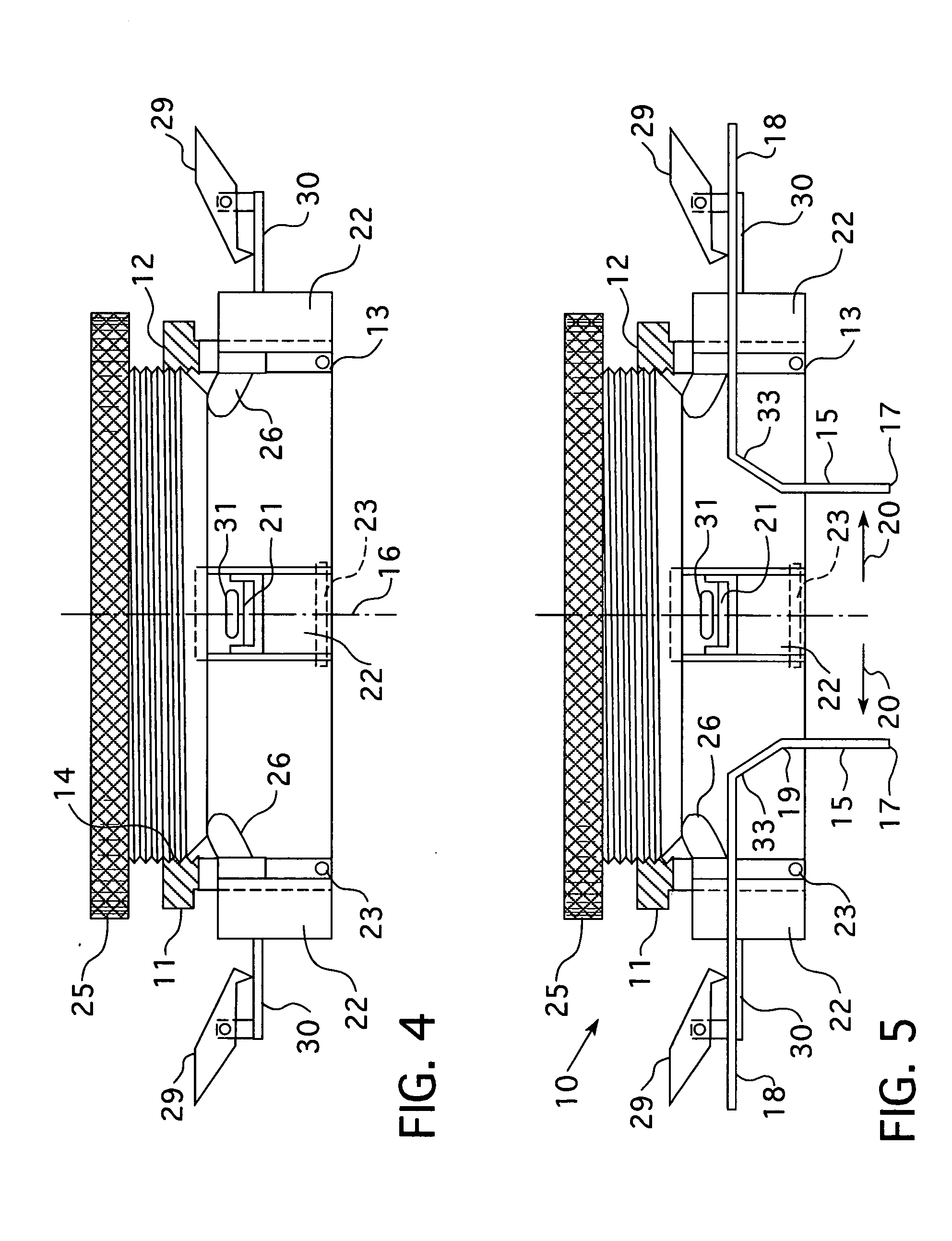
[0030]The surgical retractor 10 of the present invention is comprised of a proximal base frame 11 having a top 12 and a bottom 13 and an opening 14 for overlying an operative site on a patient. The retractor 10 is provided with a plurality of tissue engaging retractor blades 15 disposed in an array about central axis 16. The retractor blades 15 also extend downwardly from frame 11 about central axis 16 to their distal ends 17. Each blade 15 is provided with an outwardly and generally horizontally extending blade handle 18 at the proximal ends 19 of the blades. The handles 18 are slidably mounted to frame 11 whereby the blades may be selectively retracted by the handles 18 from central axis 16 as illustrated by the arrows 20 for retracting tissue.

[0031]Blade handles 18 pass through respective guide slots 21 of frame 11. Actually the guide slots 21 are provided in respective...


PUM


Abstract

The surgical retractor of the present invention includes a proximal base frame having an opening for overlying an operative site on a patient. A plurality of tissue engaging retractor blades are arrayed and disposed about and extend downwardly from the frame about a central axis of the opening to distal blade ends. Each blade has an outwardly and generally horizontally extending blade handle at their proximal ends which handles are slidably mounted to the frame whereby the blades may be selectively retracted by the handles from the central axis for thereby retracting tissue. The blade handles pass through guide slots in the frame, and more particularly through guide slots provided in respective pivotal segments that are pivotally secured to the frame on respective horizontal axes thereby the blades may be thereby independently pivoted downwardly and outwardly from the central axis. An internally opened expansion collet is coaxially received in the top of the frame for adjustable coaxial advancement downwardly into the frame. The collet is dimensioned for simultaneous engagement of selected of the pivotal segments for thereby simultaneously urging them together with their respective blades downwardly and outwardly away from the central axis to further retract tissue.

Description

BACKGROUND OF THE INVENTION[0001]The present invention relates to expandable retractors for use in surgery. More particularly, the present inventions relates to mechanical selectively expandable retractors for removing subsurface tissue in surgery performed percutaneously through a stab incision for performing minimally invasive surgical techniques.[0002]Traditional open surgical procedures performed on locations deep within the body can cause significant trauma to the intervening tissues. Such procedures often require a long incision, extensive muscle stripping, prolong retraction of tissues, denervation and devascularication of tissue. These traditional open surgeries can require extensive operating time and extensive post-operative recovery time, and in some cases, can lead to permanent scarring and more severe pain to the patient.[0003]Accordingly, minimally invasive surgical procedures are preferred. Such minimal access procedures require a device to expose the operable field w...

Claims


Application Information

Patent Timeline
Patent Type & Authority Applications(United States)
IPC IPC(8): A61B1/32
CPCA61B17/0293A61B2017/00407A61B2017/00367
Inventor DALTON, BRIAN E.
Owner DALTON BRIAN E
Why Eureka
Try Eureka