
Retractor

a retraction device and jack technology, applied in the field of retraction devices, can solve the problems of significant patient trauma and discomfort, life-threatening complications, and incisions made over the chest that are particularly painful, and achieve the effect of avoiding jack slippag

Active Publication Date: 2010-12-09
CARDIOPRECISION
View PDF45 Cites 81 Cited by
  • Summary
  • Abstract
  • Description
  • Claims
  • Application Information

AI Technical Summary

Benefits of technology

[0034]Known illuminated retractors may generate glare through reflection of light from body tissues at some stage of the procedure e.g. during insertion of the instrument, and any such impediment to the vision of a surgeon as user of the instrument causes delay in the procedure and increases risk to the patient undergoing the procedure.
[0103]Optionally filters are employed with the light source to reduce the transmission of excessive heat to the operating site.

Problems solved by technology

Conventional open-sternum surgery inflicts significant patient trauma and discomfort, requires extensive recuperation times, and may result in life-threatening complications.
Incisions made over the chest are especially painful.
The pain is unavoidable because movement exacerbates pain and the chest moves with respiration.
A significant amount of blood is typically lost from the raw surfaces of the two sides of the cut sternum.
Heat loss from wet surfaces is significant from open sternal wounds.
This leads to long-term problems with stability of the chest cage or life threatening sepsis.
Finally, the division of the chest can also lead to patients suffering from neurological disorders following open chest surgery, such as numbness in the hands.
Such positioning has been found to result in less rib breakages, but the uneven pressure of the placement occasionally causes sternal fracture, leading to complications such as increased bleeding during surgery, and the need for repeated surgery to correct the sternal damage.
The latter have side effects including sedation at higher doses.

Method used


Image

  • Retractor
  • Retractor
  • Retractor

Examples


Embodiment Construction

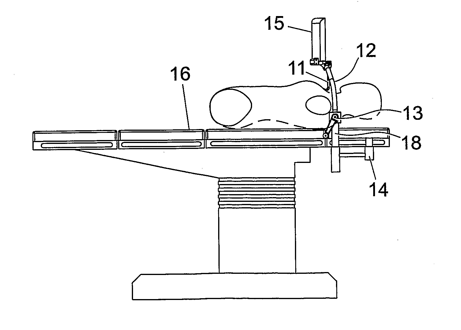
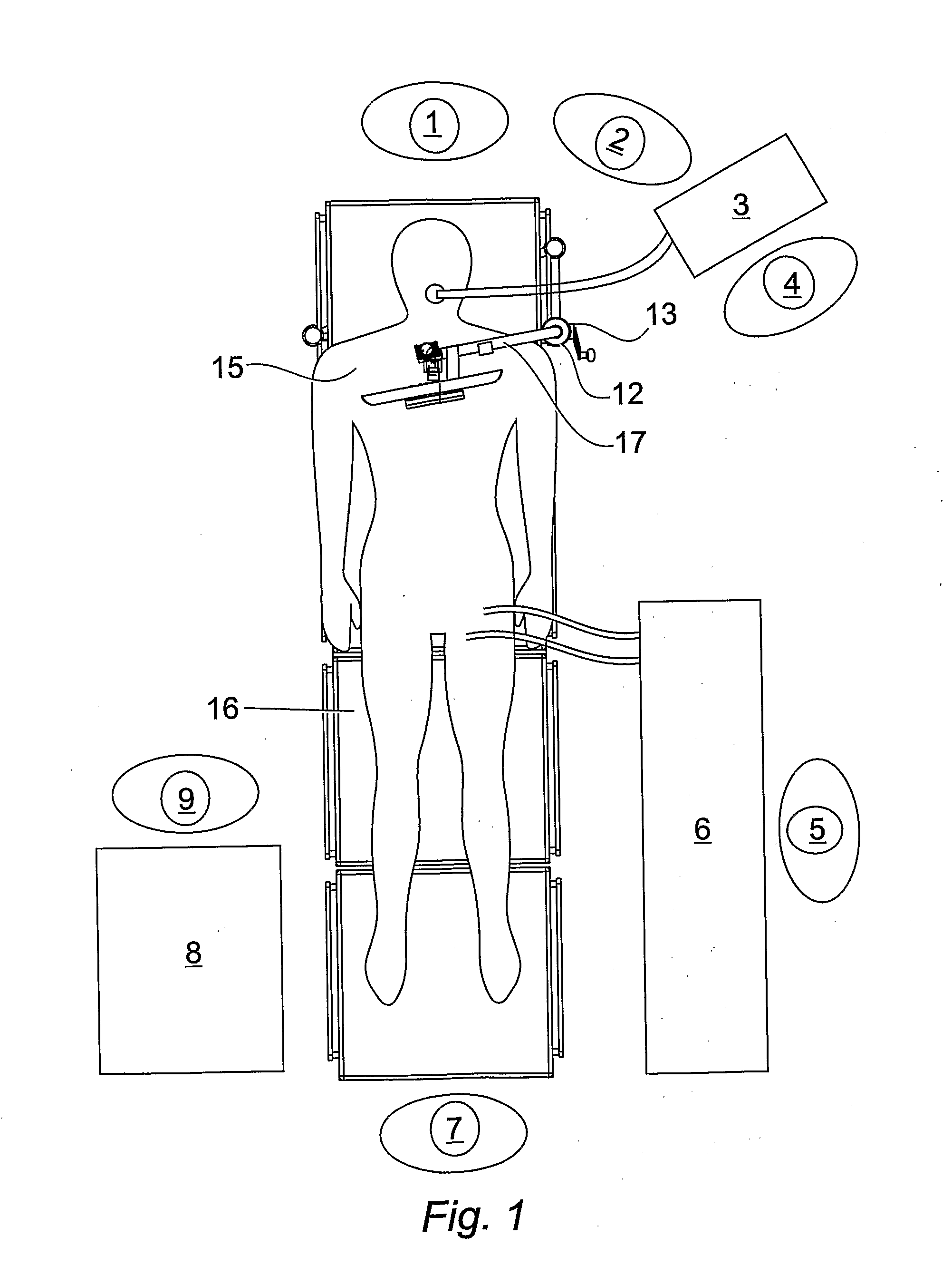
[0134]The invention as referred to in its various aspects hereinbefore is intended for use in an operating theatre where space around an operating table is limited in view of the persons in attendance and the associated equipment required to support the patient. A plan view of an operating table 16 with floorspace “footprints” occupied by medical staff and apparatus is shown in FIG. 1.

[0135]Typically, the surgeon 1 who intends to conduct the operational procedure stands at head of the operating table 16 to provide best position for access to the patient for the purposes of an aortic valve replacement procedure. The assistant surgeon 2 stands to the left of the surgeon 1. An anaesthetic machine 3 that is required to provide an accurate and continuous supply of medical gases (such as oxygen and nitrous oxide), mixed with an accurate concentration of anaesthetic vapour (such as isoflurane), for delivery to the patient at a safe pressure and flow is adjacent the head of the operating ta...


PUM


Abstract

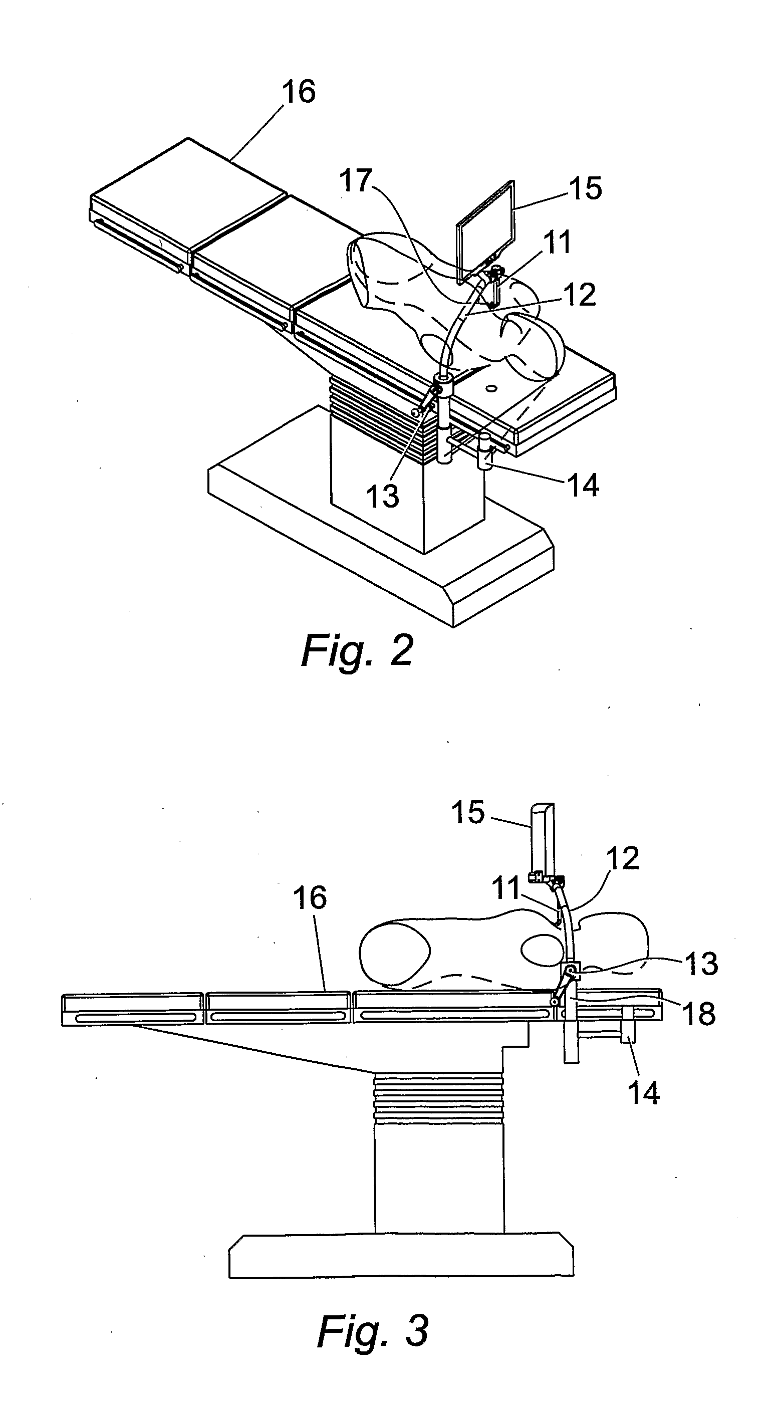
Apparatus for use in an operating theatre equipped with a surgical table, comprises a lifting frame (12) attachable to the surgical table and adapted for lifting a body part of a subject undergoing a surgical procedure upon the surgical table, and comprising an upright support post (18) incorporating a jack (54), and a lifting arm (17) pivotally mounted upon the post, whereby the arm can be turned about the upright support post on thrust bearing (57) to either overhang the surgical table, or be pivoted away to permit access to the surgical table. The arm is adapted to support a retractor that comprises a blade portion incorporating a plurality of independent lighting devices positioned in light ports (71, 72, 73) and configured to provide discrete illumination selectively to zones within the surgical field according to (a) a predetermined sequence programme, or (b) a sequence determined by a user of the retractor.

Description

[0001]The present invention relates to surgical instruments, especially to a method and device for facilitating minimally invasive cardiovascular or thoracic surgery. In particular, the invention relates to a device for expanding the thoracic basket to within its natural limits of expansion, directionally illuminating the chest cavity and providing surgical instrumentation to the surgical field.BACKGROUND[0002]In most incidences of thoracic surgery, including cardiovascular surgery, the operation necessitates the surgical division of the patient's sternum, such that the thoracic basket, or rib cage, can be prised apart. The division of the rib cage allows the surgeon access to the patient's thoracic cavity.[0003]To effect the division of the sternum, generally, the patient's sternum is split by the use of a chest saw, and the two halves held apart using a retractor.[0004]From the clavicle downwards, there are three main parts of the sternum—the manubrium, body and the xiphoid proces...

Claims


Application Information

Patent Timeline
Patent Type & Authority Applications(United States)
IPC IPC(8): A61B1/32A61G13/06
CPCA61B17/0218A61B17/0281A61B19/26A61B19/52A61B2017/00017A61B19/5212A61B2019/5206A61B2019/521A61B2019/5229A61B1/32A61B19/5202A61B2017/0237A61B90/36A61B90/30A61B2090/309A61B90/361A61B90/50A61B2090/306A61B2090/372A61B90/35
Inventor SUTHERLAND, YINGSUTHERLAND, FRASER WILLIAM HAVERN
Owner CARDIOPRECISION
Learn More