Method for providing an insulated electric high voltage DC cable or a high voltage DC termination or joint

a high-voltage dc cable and high-voltage technology, applied in the direction of insulated conductors, cables, insulating conductors, etc., can solve the problems of space charge accumulation, inability to obtain the full potential of full-size cables, space charge distortion, etc., to achieve stable and consistent dielectric properties, low tendency to space charge accumulation, and high and consistent electric strength

Active Publication Date: 2010-12-16
NKT HV CABLES AB
View PDF13 Cites 25 Cited by
  • Summary
  • Abstract
  • Description
  • Claims
  • Application Information

AI Technical Summary

Benefits of technology

[0011]Thus it is desirous to provide a process for production of an insulated DC cable with an extruded polymer based electrical insulation system suitable for use as a transmission and distribution cable in networks and installations for DC transmission and distribution of electric power. The process for application and processing of then extruded insulation system shall preferably be carried out in a manner such that there is no need for any lengthy time consuming batch-treatment. (e.g. heat treatment) of the cable to ensure stable and consistent dielectric properties and a high and consistent electric strength of the cable insulation. The resulting cable insulation shall furthe

Problems solved by technology

However, it has not been possible to obtain the full potential of these materials for full size cables.
Such space charges distort the stress distribution and persist for long periods because of the high resistivity of the polymers.
Thus, the design field for cable insulation must include a safety factor taking account for this considerably higher field resulting in the use of thicker and/or more expensive materials in the cable insulation.
The build up of the space charge accumulation is a slow process, and therefore this problem is accentuated when the polarity of the cable after being operated for a long period of time at same polarity is reversed.
However, in reality it is always next to impossible to forecast all possible side effects of a change in the system o

Method used


Image

  • Method for providing an insulated electric high voltage DC cable or a high voltage DC termination or joint
  • Method for providing an insulated electric high voltage DC cable or a high voltage DC termination or joint
  • Method for providing an insulated electric high voltage DC cable or a high voltage DC termination or joint

Examples


Embodiment Construction

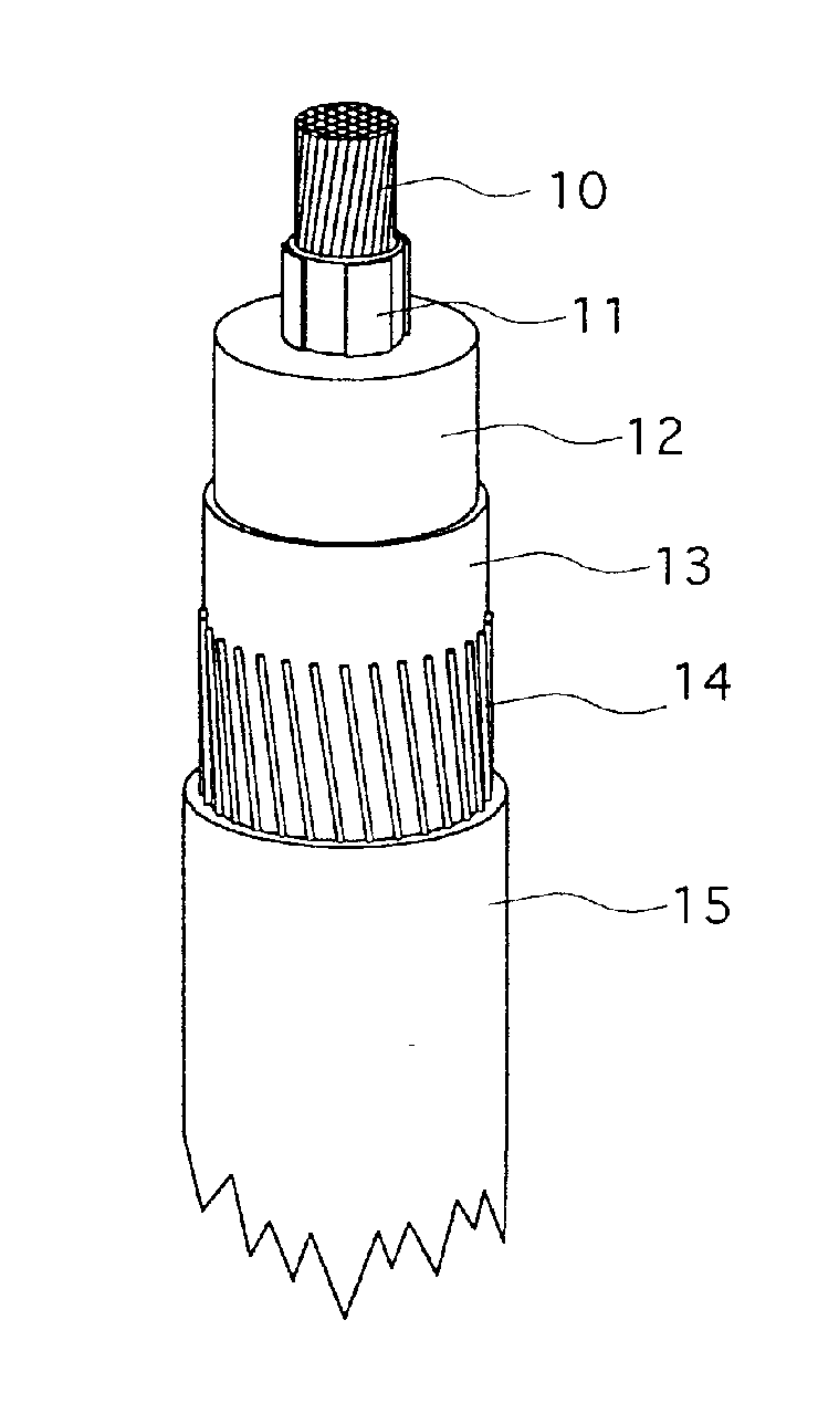
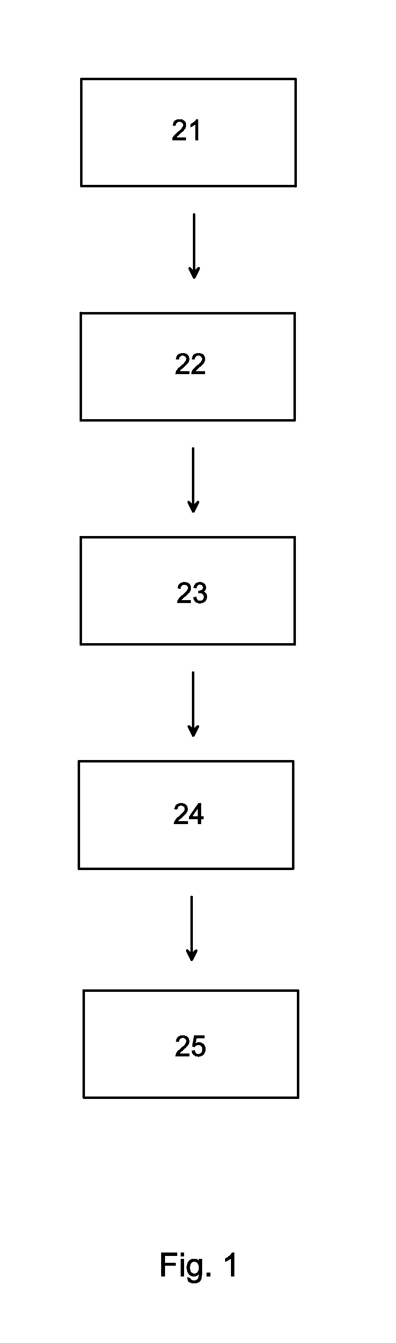
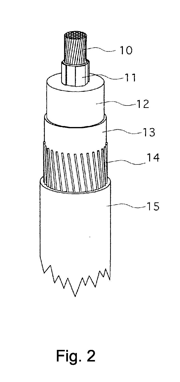
[0024]A method for production of an insulated electric high voltage DC cable according to an embodiment of the present invention will now be described with reference to FIGS. 1 and 2. The latter Figure shows the insulated electric high voltage DC cable in a section view. The DC cable comprises from the center and outwards: a stranded multi-wire conductor 10, a first extruded semi-conducting shield 11 disposed around and outside the conductor 10, an extruded polyethylene based conductor insulation 12 with an extruded, cross-linked composition as further described below, a second extruded semi-conducting shield 13 disposed outside the conductor insulation 12, a metallic screen 14, and an outer covering or sheath 15 arranged outside the metallic screen 14.

[0025]The DC cable can when found appropriate be further complemented in various ways with various functional layers or other features. It can for example be complemented with a reinforcement in form of metallic wires outside the oute...


PUM

PropertyMeasurementUnit
Temperatureaaaaaaaaaa

Abstract

A method for providing an insulated electric high voltage DC cable or a high voltage DC termination or joint. A polymer based insulation system including a compounded polymer composition is provided. The polymer based insulation system is subsequently exposed to a heat treatment procedure while the outer surface of the polymer based insulation system is covered by a cover impermeable to a substance present in the polymer based insulation system in a non-homogenous distribution, thereby equalizing the concentration of the substance in the polymer based insulation system.

Description

TECHNICAL FIELD OF THE INVENTION[0001]The present invention relates generally to high voltage electrical power equipment. More particularly, the invention relates to a method for providing an insulated electric high voltage DC cable or a high voltage DC termination or joint.DESCRIPTION OF RELATED ART AND BACKGROUND OF THE INVENTION[0002]Extruded solid insulation based on a polyethylene, or a cross linked polyethylene (XLPE), has for almost 40 years been used for AC transmission and distribution cable insulation.[0003]Therefore the possibility of the use of XLPE for DC cable insulation has been under investigation for many years. Cables with such insulations have the same advantage as the mass impregnated cable in that for DC transmission there are no restrictions on circuit length and they also have a potential for being operated at higher temperatures, thus offering a possibility to increase the transmission load.[0004]However, it has not been possible to obtain the full potential ...

Claims


Application Information

Patent Timeline
IPC IPC(8): H01B13/32
CPCH01B3/441H02G15/18H02G15/003H02G1/14
Inventor OLSSON, CARL-OLOF
Owner NKT HV CABLES AB
Why Eureka
Try Eureka