
Power tool

a technology of power tools and power tools, applied in the field of power tools, can solve the problems of severe impairment of the functioning of the power tool, increased demands on the power tool, and the failure of the technique, and achieve the effect of reducing such impairments of the power tool and effective mechanical damping of the electromechanical

Active Publication Date: 2010-12-16
MARQUARDT GMBH SCHLOSSTRASSE 16 7201 RIETHEIM-WEILHEIM 1 WEST GERMANY
View PDF19 Cites 55 Cited by
  • Summary
  • Abstract
  • Description
  • Claims
  • Application Information

AI Technical Summary

Benefits of technology

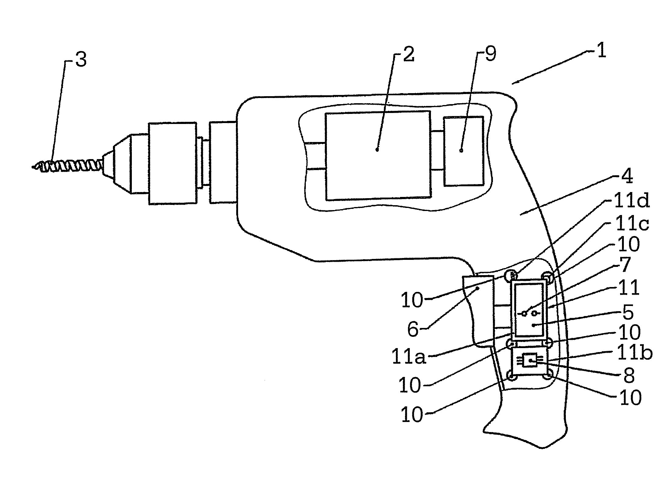
[0007]The object of the invention is to largely prevent, but at least reduce, such impairments in the power tool that are caused by vibration. In particular, effective mechanical damping of electromechanical and / or electronic switching elements inside the handle shell of the power tool is to be realized.
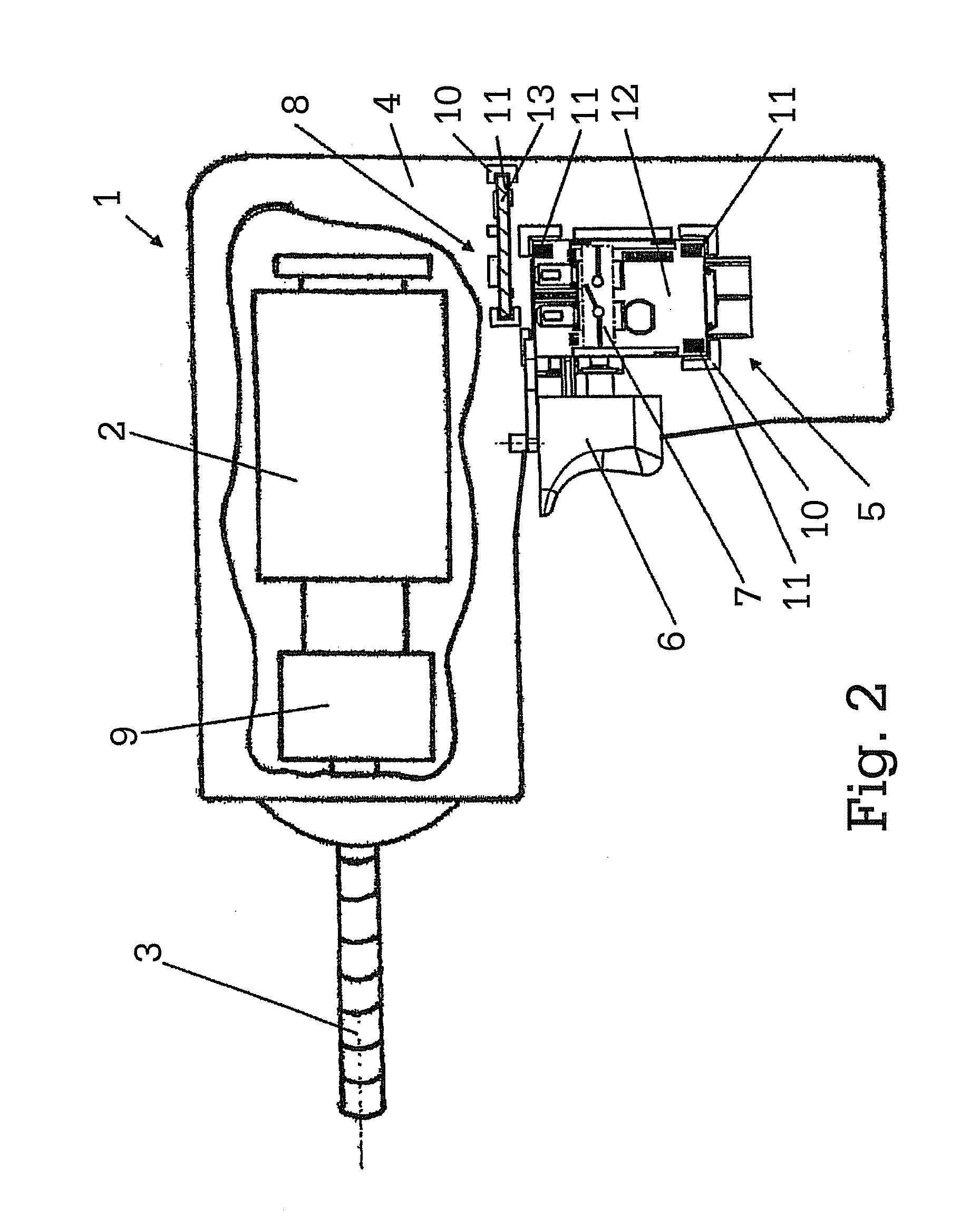
[0008]In the power tool according to the invention, a vibration isolator is arranged between the receptacle in the housing and the electric and / or electronic module. Effective damping for the module is thereby achieved, as a result of which the robustness of the module is optimized, which increases its functional reliability even during heavy duty application of the power tool.
[0009]The electric and / or electronic module can be an electronic switch having an electromechanical contact system. The module can just as easily be an electronic switch in which the switching function is realized electronically by means of semiconductors. The switch has a switch housing for accommodating these switch components. An electronic unit for controlling the electric motor can also be located in the switch housing, whereby, for example, the speed, the torque, or the like, of the power tool can be set. The vibration isolator is then arranged on the switch housing in such a way as to face the receptacle, whereby the electric switch is largely protected from the effect of vibrations of the power tool. Although the vibration isolator can be arranged loosely on the switch housing, it is expediently fastened to the switch housing.

Problems solved by technology

This in turn increases the demands made on the power tool, on its modules and on its individual parts with regard to resistance and robustness in the face of such pronounced vibrations.
This technique, however, has only been moderately successful.
Vibration resistance is an important technical challenge nowadays, and will become increasingly so in the future.
Without further measures with regard to the vibration resistance, severe impairment of the functioning of the power tool, from the release of connections and electrical contacts right through to partial destruction of individual parts may occur.
Thus, for example, closed power contacts may lose their contact stability, electronic components may be shaken off or metal heat sinks can become detached from their respective fastenings.

Method used


Image

  • Power tool
  • Power tool
  • Power tool

Examples


Embodiment Construction

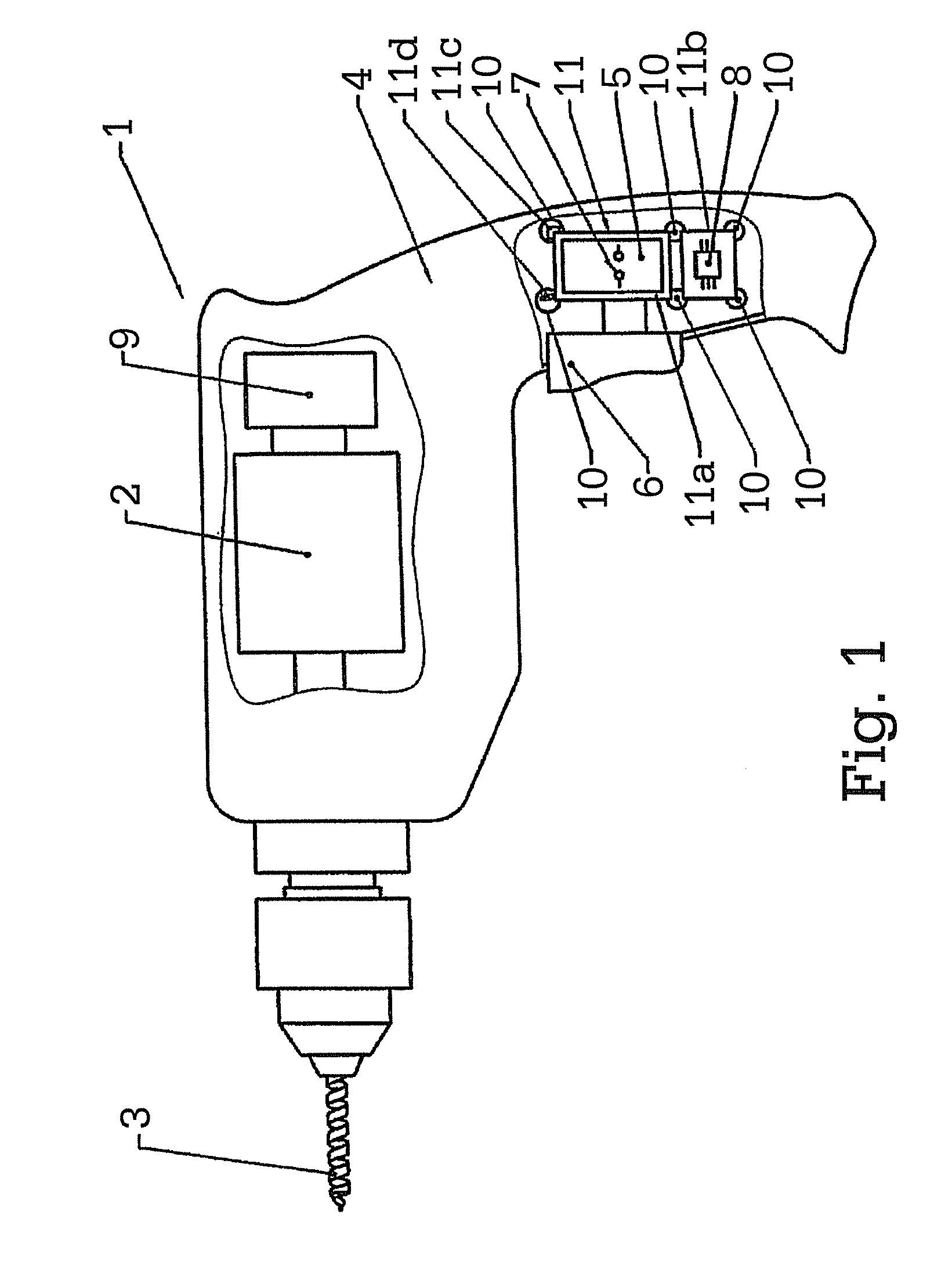
[0031]A power tool 1 having an electric motor 2 for driving a tool 3 can be seen in FIG. 1. The power tool may be a cordless and / or mains-operated power tool. By way of example, a percussion drilling machine is shown as power tool 1 in FIG. 1. Of course, the power tool 1 may also be an impact screwdriver, a sabre saw, a sander or the like. A vibration-generating device 9, such as a percussion mechanism, is connected to the electric motor 2 or, in another manner, to the tool 3.

[0032]A switch 5 is arranged in the housing 4 of the power tool 1. The switch 5 is accommodated in the housing 4 in such a way that an actuating member 6, which can be moved manually by the user, of the switch 5 projects from the housing 4. The switch 5 has a contact system 7, on which the actuating member 6 acts for switchover, such that the power tool 1 can be switched on and / or off by means of the actuating member 6. Finally, an electric circuit arrangement for controlling the electric motor 2 is assigned to...


PUM

PropertyMeasurementUnit
Elasticityaaaaaaaaaa

Abstract

The invention relates to a power tool, such as an impact drilling machine, impact screwdriver, saber saws, grinders, or the like, comprising a housing. In the housing, an electric motor and an electric or electronic module that is attached to holders in the housing, for example, an electric switch or electronics, are provided. Between the holders in the housing and the electrical or electronic modules, a vibration decoupling element is disposed.

Description

CROSS REFERENCE TO RELATED APPLICATIONS[0001]This application is a continuation of International Application No. PCT / DE2008 / 002147 filed Dec. 29, 2008, which designated the United States, and claims the benefit under 35 USC §119(a)-(d) of German Application No. 10 2008 003 709.5 filed Jan. 9, 2008, the entireties of which are incorporated herein by reference.FIELD OF THE INVENTION[0002]The invention relates to a power tool.BACKGROUND OF THE INVENTION[0003]A portable power tool can be a percussion drilling machine, an impact screwdriver, a sabre saw, a sander or the like.[0004]Such power tools have a housing and an electric motor located in the housing. Furthermore, there are located in the housing electric and / or electronic modules, for example, an electric and / or electronic switch, an electronic unit for controlling the electric motor, or the like, the electric and / or electronic module being fastened to one or more receptacles in the housing.[0005]Power tools in particular for mech...

Claims


Application Information

Patent Timeline
IPC IPC(8): B25F5/02
CPCB25F5/006
Inventor MULLER, JENSGASSER, STEPHAN
Owner MARQUARDT GMBH SCHLOSSTRASSE 16 7201 RIETHEIM-WEILHEIM 1 WEST GERMANY
Learn More