Radome and Shroud Enclosure for Reflector Antenna

a reflector antenna and shroud enclosure technology, applied in the direction of antennas, antenna details, antenna couplings, etc., can solve the problems of increased manufacturing complexity and/or cost, unusable backlobes into the signal pattern of the reflector antenna, and the need for metalizing operations,

Active Publication Date: 2010-12-16
COMMSCOPE TECH LLC
View PDF17 Cites 86 Cited by
  • Summary
  • Abstract
  • Description
  • Claims
  • Application Information

AI Technical Summary

Problems solved by technology

Significantly, edges parallel to the signal path, such as the distal edge of a cylindrical shroud, are known to diffract signal energy present in this area, introducing undesirable backlobes into the reflector antenna signal pattern.
However, the required metalizing operations may increase manufacturing complexity and / or cost, including elaborate coupling arrangements configured to securely retain the shroud upon the reflector dish without presenting undesired reflection edges and / or extending the overall size of the radome.
Further, the thin metalized ring layer applied to the periphery of the radome may be fragile, requiring increased care to avoid damage during delivery and / or installation.
The addition of a shroud to a reflector antenna improves the signal pattern generally as a function of the shroud length, but also similarly introduces significant costs as the increasing length of the shroud also increases wind loading of the reflector antenna, requiring a corresponding increase in the antenna and antenna support structure strength.

Method used


Image

  • Radome and Shroud Enclosure for Reflector Antenna
  • Radome and Shroud Enclosure for Reflector Antenna
  • Radome and Shroud Enclosure for Reflector Antenna

Examples


Embodiment Construction

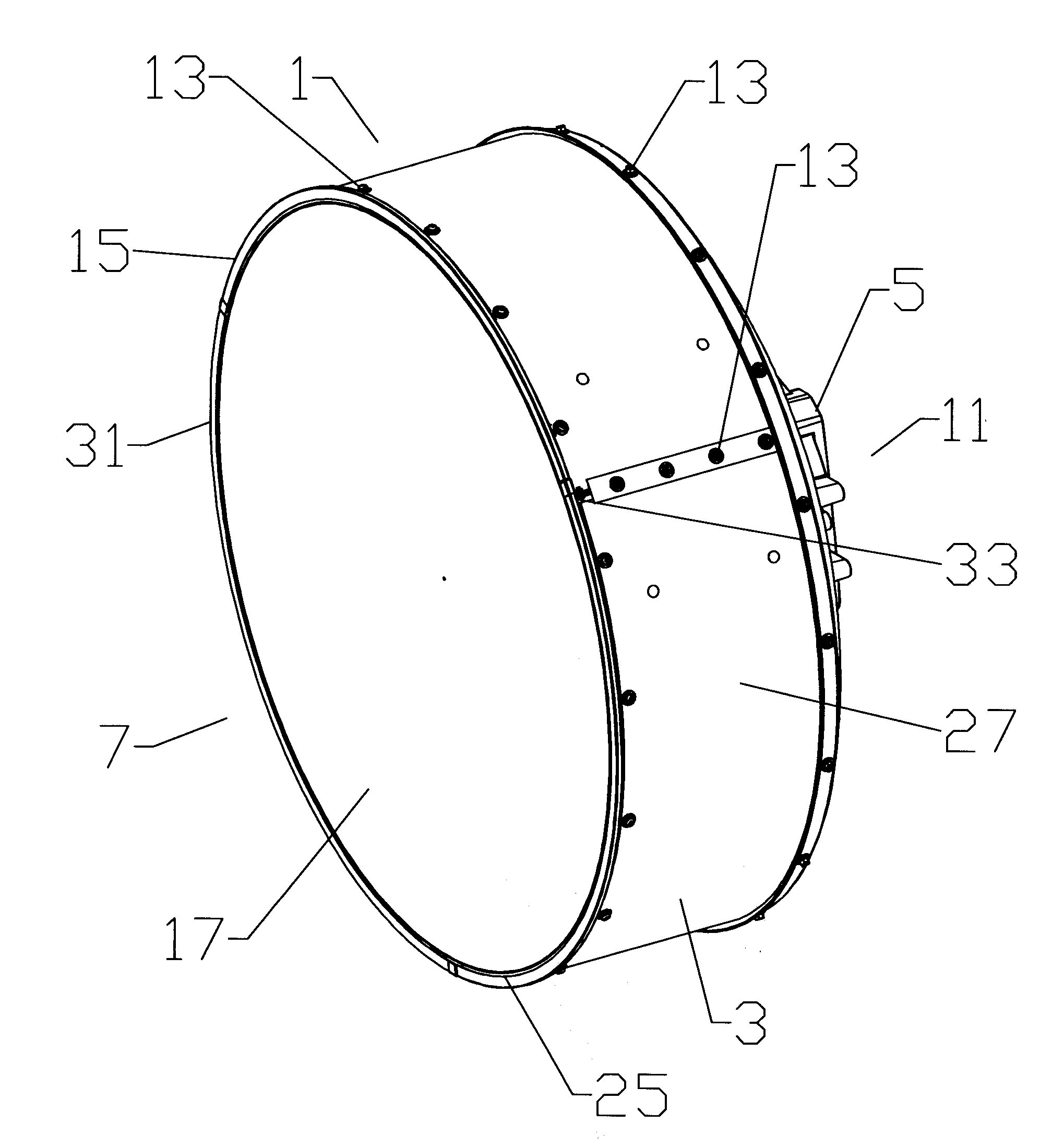
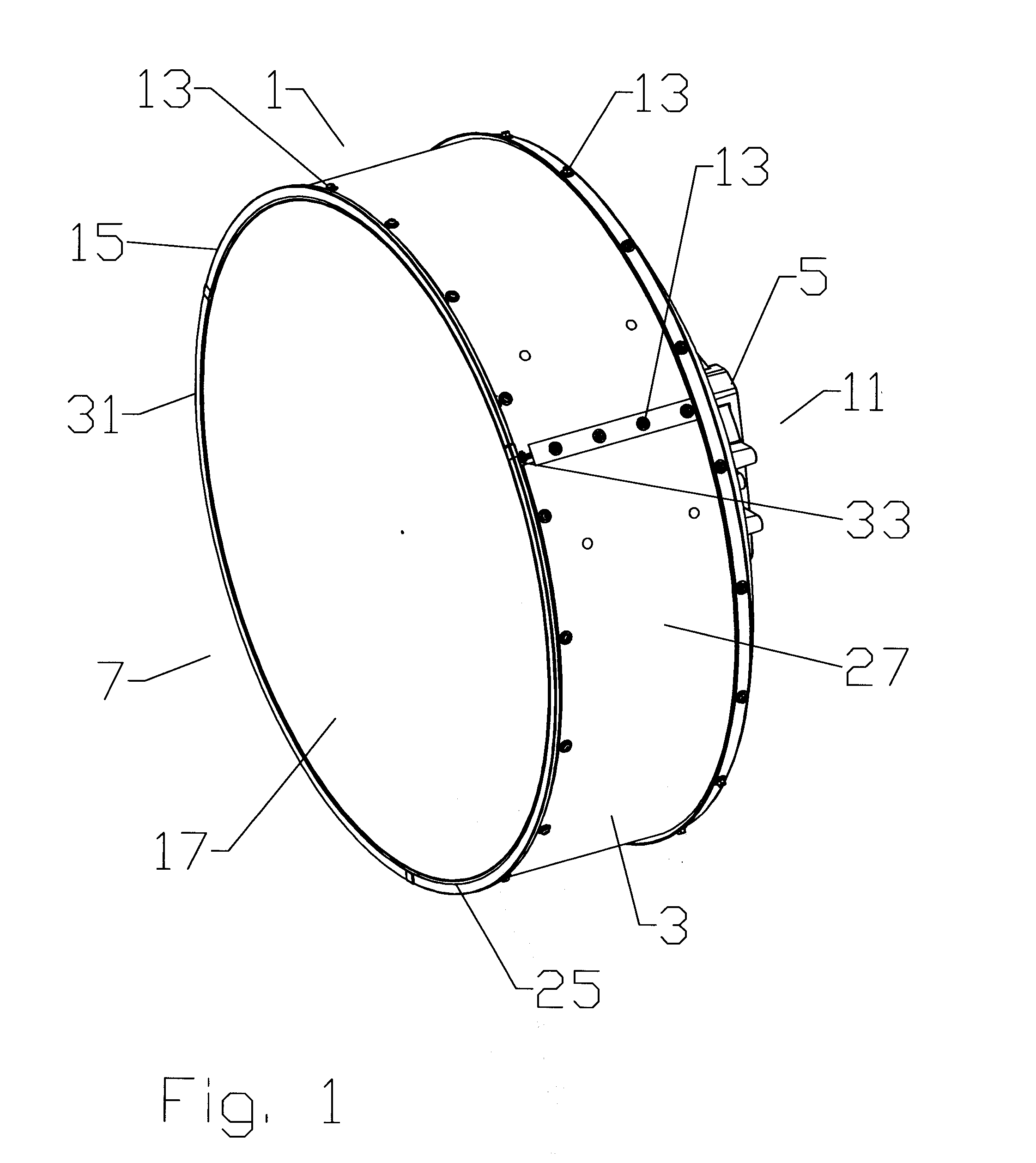
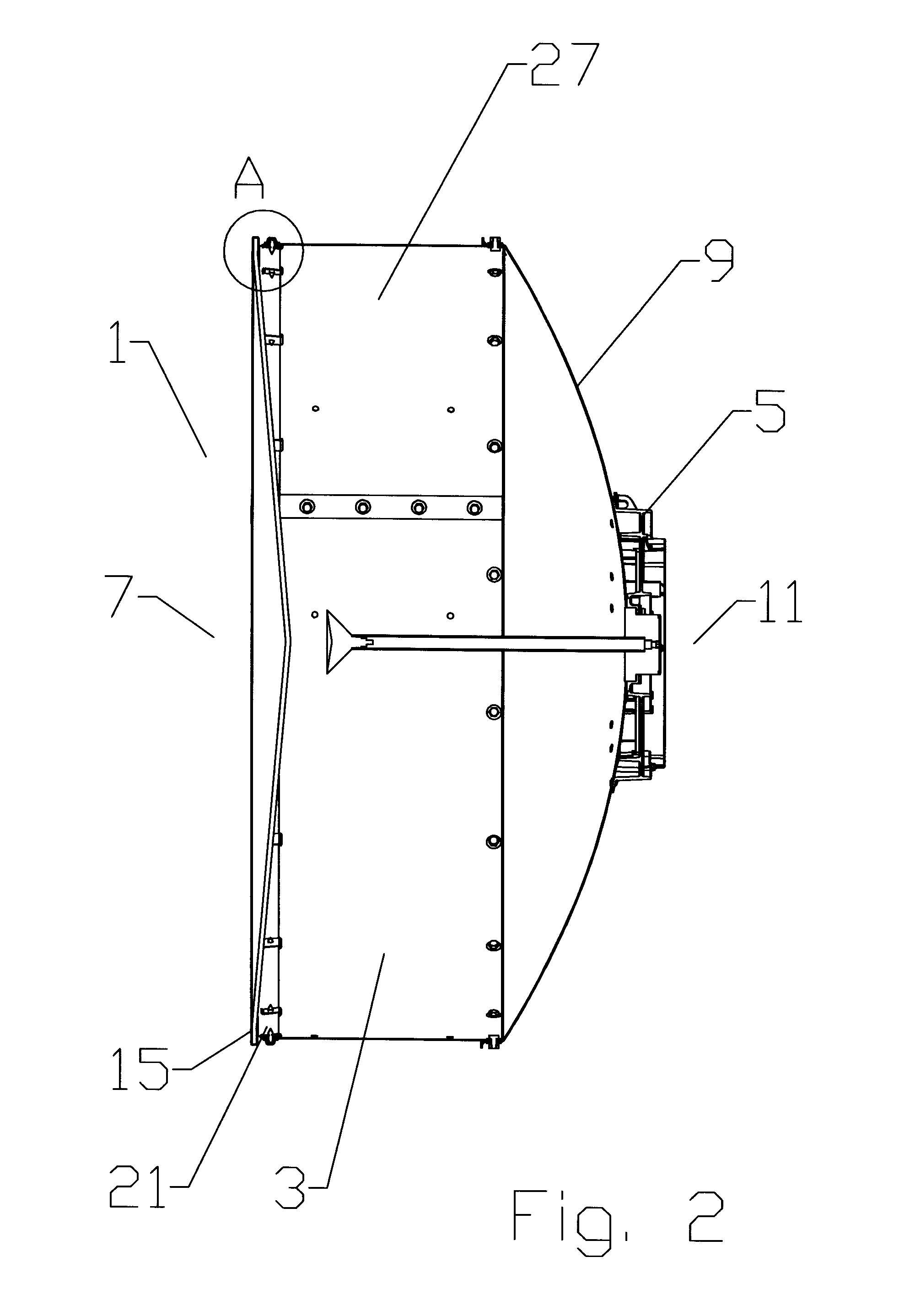
[0021]A first exemplary embodiment of a reflector antenna enclosure 1 is demonstrated in FIGS. 1-11. A cylindrical shroud 3 extends, generally coaxial with a longitudinal axis of the reflector antenna 5, from a distal end 7 of the reflector dish 9. A proximal end 11 of the shroud 3 is coupled, for example via mechanical fastener(s) 13 or the like, to the periphery of the reflector dish 9. A retaining band 15 may be coupled to an inner diameter of the shroud 3, proximate the distal end 7 of the shroud 3. A radome 17 enclosing the distal end 7 of the shroud 3 cavity is seated within a retaining groove 19 of the retaining band 15.

[0022]The retaining band 15 has a cross section best demonstrated in FIG. 3. A mounting portion 21 of the retaining band 15 is coaxial with the shroud 3, dimensioned to seat against the inner diameter of the distal end 7 of the shroud 3, fastened for example by a plurality of fastener(s) 13 each threaded into a respective clip 16 placed upon the mounting porti...


PUM

PropertyMeasurementUnit
inner diameteraaaaaaaaaa
outer diameteraaaaaaaaaa
diameteraaaaaaaaaa

Abstract

An enclosure for the open end of a reflector antenna includes a cylindrical shroud coupled to a distal end of the reflector antenna, the shroud generally coaxial with a longitudinal axis of the reflector antenna. A retaining band is coupled to an inner diameter of the shroud, proximate a distal end of the shroud. The retaining band is provided with a retaining groove open radially inward towards the longitudinal axis. The retaining groove provided with a bottom extending radially outward beyond an outer diameter of the shroud. A radome is seated within the retaining groove.

Description

BACKGROUND[0001]1. Field of the Invention[0002]This invention relates to microwave reflector antennas. More particularly, the invention relates to a radome and shroud enclosure for reflector antennas with improved signal pattern and mechanical characteristics.[0003]2. Description of Related Art[0004]The open end of a reflector antenna is typically enclosed by a radome coupled to the distal end of the reflector dish and / or of a cylindrical shroud extending from the reflector dish.[0005]The radome provides environmental protection and improves wind load characteristics of the antenna. Precision shaping may be applied to the radome to compensate for signal trajectory and / or reflection effects resulting from an impedance discontinuity introduced into the signal path of the reflector antenna by the presence of the radome. Edge(s) of the radome attachment arrangement scatter the RF signal degrading the signal pattern. Significantly, edges parallel to the signal path, such as the distal ed...

Claims


Application Information

Patent Timeline
Patent Type & Authority Applications(United States)
IPC IPC(8): H01Q1/42H01P11/00H01Q1/52
CPCH01Q1/42H01Q17/00H01Q19/134Y10T29/49016
Inventor SYED, JUNAIDLEWRY, MATTHEWRENILSON, IANSIMMS, STEPHEN
Owner COMMSCOPE TECH LLC
Why Eureka
Try Eureka