Forming light beams and patterns with zero intensity central points

a technology of central points and light beams, applied in the field of optical devices, can solve the problems of spurious reflection, insufficient correction, limited effective resolution,

Active Publication Date: 2010-12-16
BAER
View PDF16 Cites 19 Cited by
  • Summary
  • Abstract
  • Description
  • Claims
  • Application Information

AI Technical Summary

Benefits of technology

[0010]One object of the present invention is to provide a method of producing beams with an intensity distribution having a substantially zero intensity along the beam axis and / or in the beam focus, where the method allows the wavelength of the light to be changed without requiring any readjustment.
[0011]Another object of the present invention is to provide a method of producing beams with an intensity distribution having a substantially zero intensity along the beam axis and / or in the focus, where the beam has a broad spectral distribution.
[0012]Another object of the present invention is to provide a method of producing beams with an intensity distribution having a substantially zero intensity along the beam axis and / or in the focus which allows laser beams to be converted to such beam without requiring any beam expansion.
[0013]Another object of the present invention is to provide a method of producing beams with an intensity distribution having a substantially zero intensity along the beam axis and / or in the focus that consists of just transparent elements with parallel surfaces.
[0014]Another object of the present invention is to provide a device for producing beams with an intensity distribution having a substantially zero intensity along the beam axis and / or in the focus, that is sufficiently compact to be able to conveniently fit inside a microscope body, even, if necessary, close to the pupil plane of the objective lens.
[0015]A search is made for pairs of glass types that, at a particular thickness for each glass in the pair, the phase difference in propagation of light through one glass of the pair is exactly one half a wavelength relative to the other glass of the pair, for at least three different wavelengths spread out in the wavelength region of difference. Where one glass of the pair is called A and has a thickness TA and the other glass is B and has a thickness TB, eight squares of glass are made, two squares “A” of glass A of thickness TA, two squares “A*” of glass A of thickness TA / 2, two squares “B” of glass B of thickness TB and two squares “B*” of glass B of thickness TB / 2. Then four sandwiches of the squares are arrayed in a 2×2 quadrant square with a sandwich of glass A and A* in the upper left hand quadrant, of glass B and B* in the upper right hand quadrant, of glass B and A* in the lower right hand quadrant and of glass A and B* in the lower left hand quadrant. This array is then placed in the optical axis at either a pupil plane, a real image plane or an intermediate plane, and illuminated by a plane wave, perhaps having a Gaussian intensity profile. The light emerging from the array will have the desired properties of a zero intensity central axis and / or central point in an image plane, for the chosen wavelengths for which the half wavelength difference was exact, and close to a zero intensity for the intermediate wavelengths. This description describes several variations of this basic scheme.

Problems solved by technology

This leads to resolution limited effectively only by the ability to generate the high powers of the doughnut-shaped beam and the ability of the specimen to tolerate the high powers.
However, because in this application, phase errors of even a small fraction of a wavelength can be detrimental to the performance of the system, such correction is not always adequate, particularly over a large wavelength range.
However this proposed solution involves introducing additional optics to direct the beam onto the SLM and pass the reflected beam to the rest of the system, and in some cases to expand the beam for presentation to the SLM and to contract it for presentation to the rest of the optical system, and such optics create an opportunity for scattering, spurious reflection and introduction of additional phase errors.
Furthermore the system is relatively expensive, and cannot deal with extremely rapid changes in wavelength required in some microscope techniques or creation of zero-center patterns from an intrinsically broadband source.
However even when a given phase plate is used with the exact wavelength for which it had been designed, it is difficult to control the thickness of the think layer coatings with sufficient accuracy to create a perfect pattern with a substantially zero intensity center.
Also it is impossible to quickly vary excitation wavelength because of the need to rotate the glass sheet to put another phase plate into position.
Furthermore the system cannot work with a broadband source.
However, with a metallic backing layer, the absorption does show a wavelength dependence, so that it is difficult or impossible to ensure cancellation at the central point over a wide range of wavelengths.
Furthermore when such a system is used in a Mach-Zehnder interferometer to approximate a circular pattern with a zero intensity center, the light at two orthogonal axes is plane polarized, which may result in incomplete quenching in a STED microscope, thereby reducing resolution.
Furthermore such a solution is bulky, and to avoid loss of alignment with even small temperature changes requires operation in a very limited temperature range.
Thus there remains an unfulfilled need for apparatus to create zero central point patterns that is compact and accurate over a wide range of wavelengths without requiring readjustment.

Method used


Image

  • Forming light beams and patterns with zero intensity central points
  • Forming light beams and patterns with zero intensity central points
  • Forming light beams and patterns with zero intensity central points

Examples


Embodiment Construction

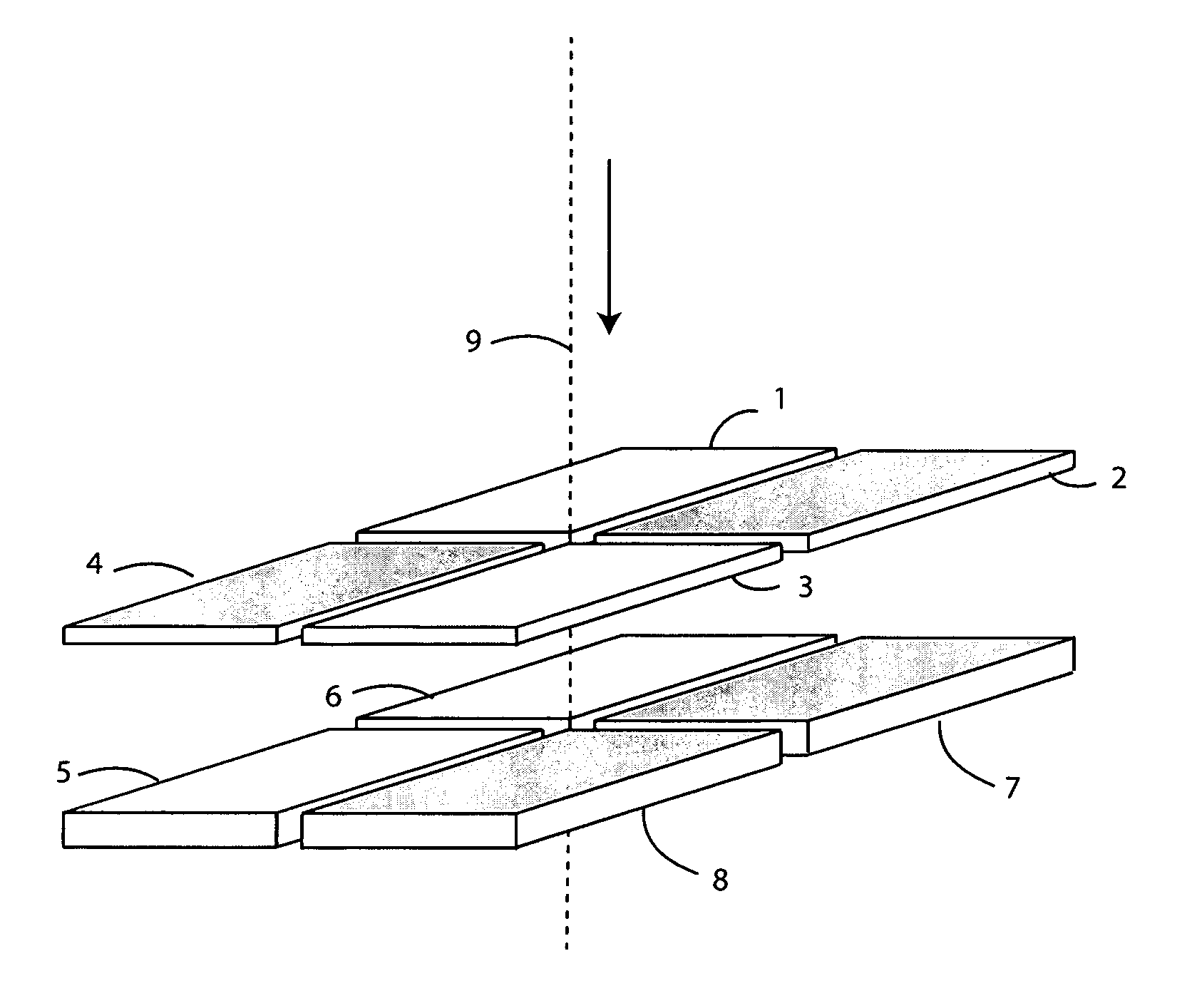
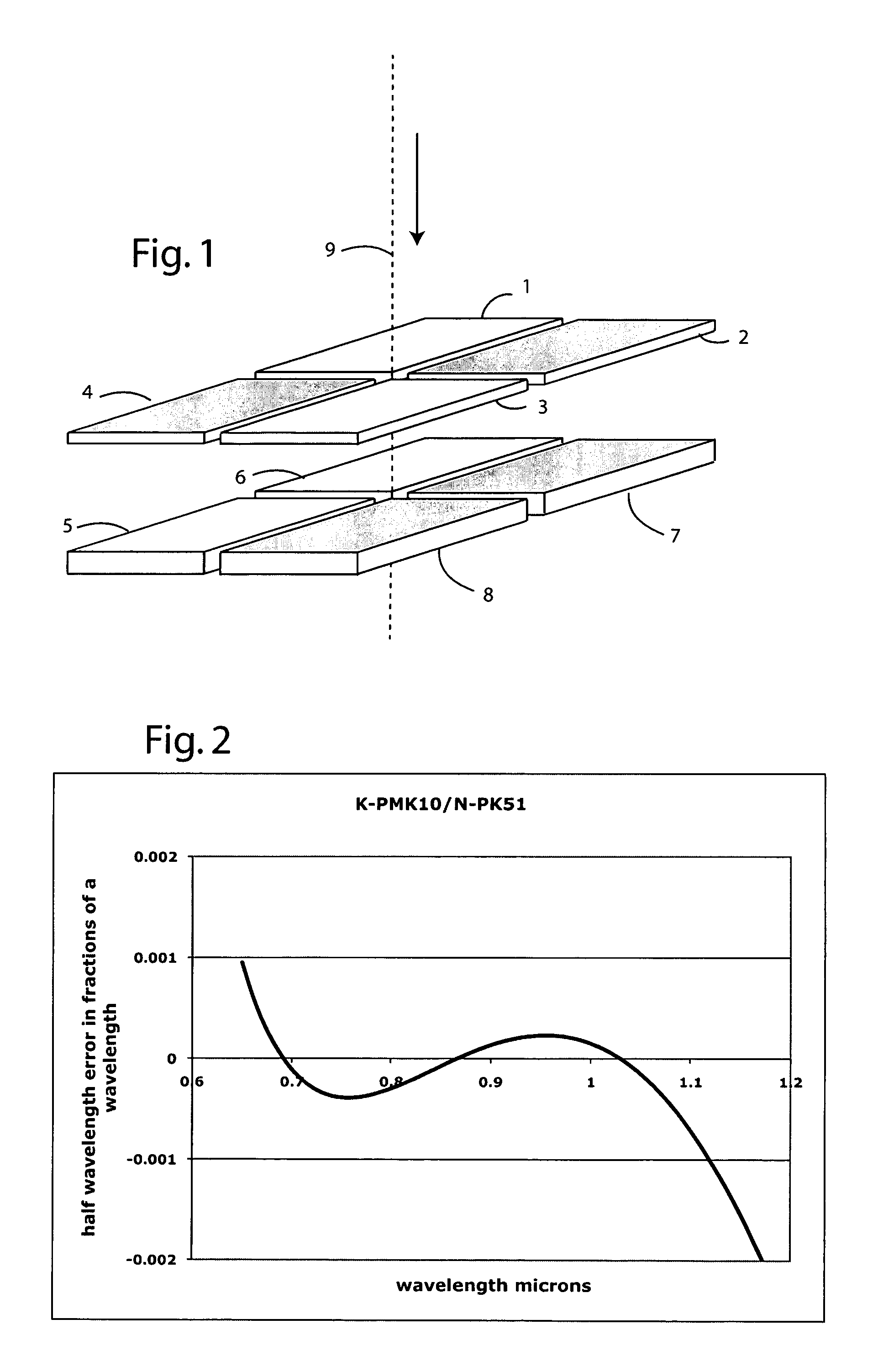
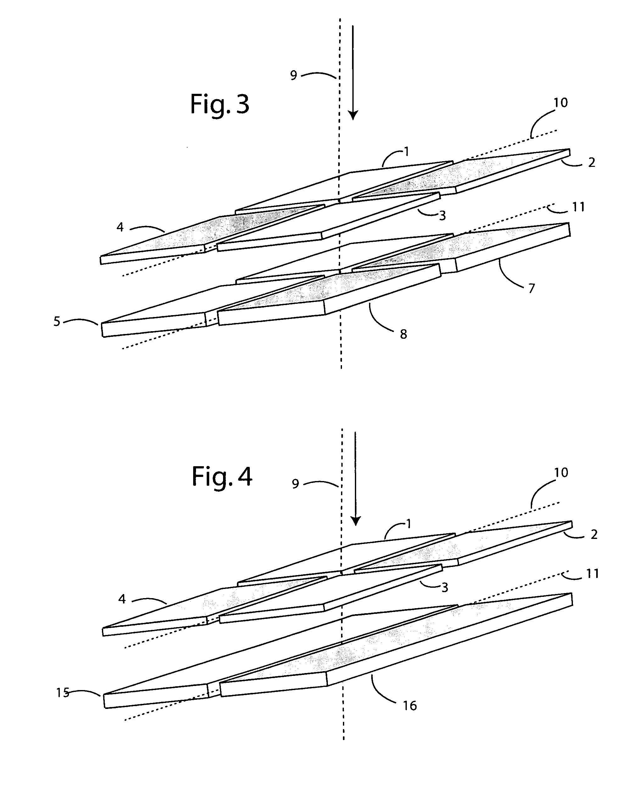
[0026]FIG. 1 shows an exemplary embodiment of the present invention, in which elements 1 through 8 are glass sheets arranged in a sandwich of two 2×2 matrices, oriented normal to a laser beam 9 shown in the drawing by just its central ray. The direction of light in beam 9 is shown by an arrow. Sheets 1 and 3 are made of Sumita K-PMK10 glass of 82.503 μm in thickness. Sheets 2 and 4 are made of Schott N-PK51 glass of 82.286 μm in thickness. Sheets 5 and 6 are made of Sumita K-PMK10 glass of 165.005 μm in thickness. Sheets 7 and 8 are made of Schott N-PK51 glass of 164.571 μm in thickness.

[0027]As will now be shown, over a large spectral range, light passing successively through sheets 1 and 6 is retarded almost exactly a half wavelength with respect to light passing successively through sheets 3 and 8. FIG. 2 shows a graph of the error as a fraction of a wavelength, plotted against wavelength, for the deviation from half wavelength relative retardation for two beams, one passing thro...


PUM


Abstract

In order to produce a beam with a zero intensity axial ray or to produce a beam that when focused will produce an image of a doughnut shaped pattern with a zero intensity central point, a beam with a uniform or Gaussian profile is directed to a plurality of transparent plates, arranged in pairs on opposite sides of the beam axis, such that for at least one pair, the plates have a composition and thickness different from each other, and chosen so that the transmitted light has a has a phase difference of half a wavelength for at least three different wavelengths. An additional plate with a center on the perpendicular of the line connecting the first two plates has a composition and thickness such that the light transmitted through that additional plate has a phase difference of a quarter wavelength with respect to the light transmitted through one of the plates of said first pair of plates, at at least one wavelength.

Description

CROSS REFERENCE TO RELATED APPLICATION[0001]This application claims priority from U.S. Provisional Patent Application Ser. No. 60 / 888,764, filed Feb. 7, 2007 and from U.S. Provisional Patent Application Ser. No. 60 / 891,046, filed Feb. 22, 2007, the entire disclosure of which is hereby incorporated by reference.FIELD OF THE INVENTION[0002]The present invention relates to optical devices, and more particularly, devices for modifying the profile of a propagating beam. Still more particularly the present invention relates to devices that create beams either having a substantially zero intensity on their propagation axis and / or that when focused have a substantially zero intensity at a central point in the plane of focus.BACKGROUND OF THE INVENTION[0003]In the STED microscope (Hell and Wichmann U.S. Pat. No. 5,731,588, Baer, U.S. Pat. No. 5,866,911), the resolution of a scanning fluorescent microscope is improved by scanning the spot of excitation light synchronously and concentrically w...

Claims


Application Information

Patent Timeline
Patent Type & Authority Applications(United States)
IPC IPC(8): G02B27/09
CPCG02B21/0032G02B27/0988G02B27/0927G01N21/64G01N2201/06113G03F7/70191
Inventor BAER, STEPHEN C.
Owner BAER
Why Eureka
Try Eureka