
Connecting rod bearing for internal combustion engines and connecting rod bearing device

a technology of connecting rod bearings and internal combustion engines, which is applied in the direction of bearings, shafts and bearings, rotary bearings, etc., can solve the problems of foreign substances damaging the sliding surface of the connecting rod bearing, damage to the bearing, and foreign substances discharge

Active Publication Date: 2010-12-16
DAIDO METAL CO LTD
View PDF6 Cites 23 Cited by
  • Summary
  • Abstract
  • Description
  • Claims
  • Application Information

AI Technical Summary

Benefits of technology

[0011]An object of the present invention is to provide a slide bearing (i.e. a connecting rod bearing) for crankpins of internal combustion engines excellent in discharge property of foreign substances which are entrained in lubricant oil fed through an internal lubricant-oil passage of a crankshaft.

Problems solved by technology

If such foreign substances entrained by the lubricant oil are fed between the crankpin and the connecting rod bearing, there is a risk that the foreign substances damage the sliding surface of the connecting rod bearing.
When the above idea is applied to the connecting rod bearing, however, it was confirmed by an experiment that not only the foreign substance discharge effect is obtainable but also the proposed way is counterproductive since the foreign substances remain in the circumferential oil groove formed throughout the entire circumferential length of the inner surface of the semi-cylindrical bearing of the connecting rod bearing, and are dispersed throughout the sliding surface of the bearing thereby becoming liable to damage the bearing.
Such a connecting rod bearing suffers increased damages as compared with a conventional connecting rod bearing without such a circumferential oil groove.
However, in a manufacturing process of internal combustion engines, when the semi-cylindrical bearings are incorporated into a split type connecting rod housing, the semi-cylindrical bearing provided with the partial circumferential groove might be erroneously incorporated such that the circumferential end, in the vicinity of which the partial circumferential groove is provided, faces a counter direction to the relative rotational direction of the crankpin.
If such an erroneous incorporation occurs, the circumferential groove will disadvantageously promote the foreign substances to move onto the sliding surface of the bearing.

Method used


Image

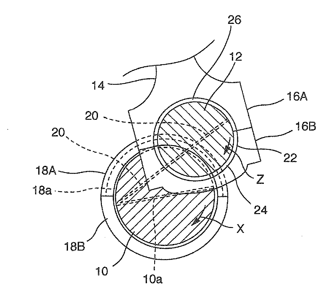
  • Connecting rod bearing for internal combustion engines and connecting rod bearing device
  • Connecting rod bearing for internal combustion engines and connecting rod bearing device
  • Connecting rod bearing for internal combustion engines and connecting rod bearing device

Examples


embodiment 1

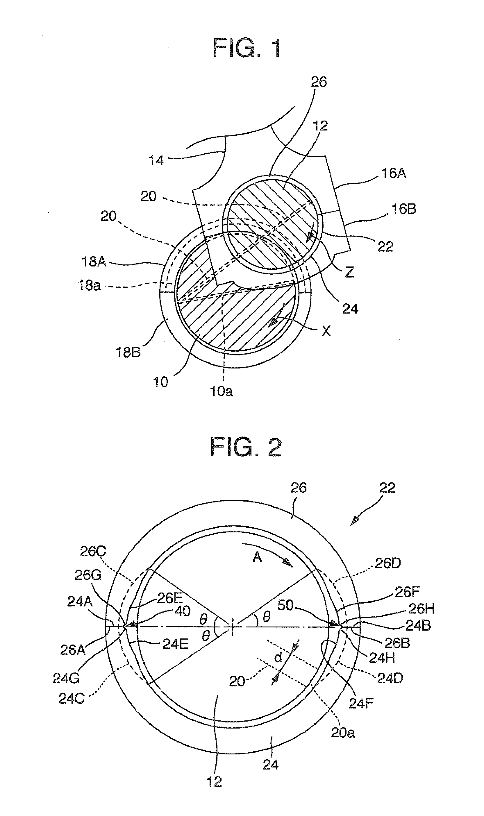
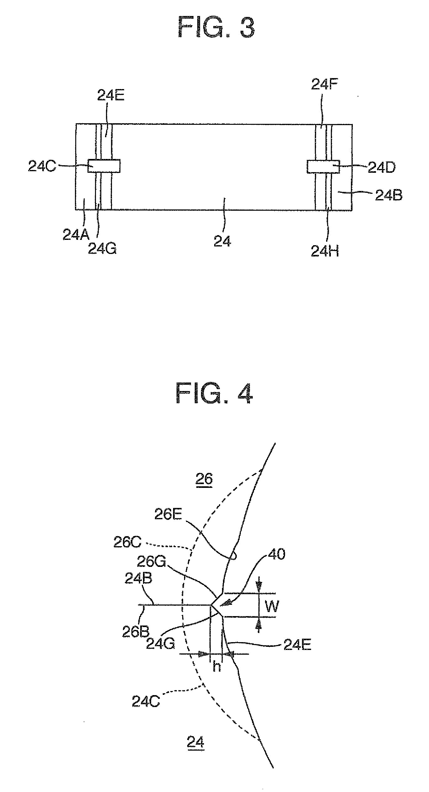
[0071]FIGS. 2 to 4 show the semi-cylindrical bearings 24 and 26 constituting the connecting rod bearing 22 in detail. Since the semi-cylindrical bearings 24 and 26 have the same form as each other, the form of only one of the semi-cylindrical bearings will be explained.

[0072]The semi-cylindrical bearing 24 is of a symmetrical member in the drawing.

[0073]Circumferential Groove:

[0074]Circumferential grooves 24C and 24D for lubricant oil having a rectangular shape in cross section are formed on the inner surface of the semi-cylindrical bearing 24, which extend from circumferential ends 24A and 24B of the semi-cylindrical bearing 24 toward the circumferential center of the semi-cylindrical bearing 24. Width center lines of the circumferential grooves 24C and 24D are in alignment with the width center line of the semi-cylindrical bearing 24, and with the opening center of a lubricant-oil outlet port 20a (i.e. the outlet port of the lubricant-oil passage 20) existing on the surface of the...

embodiment 2

[0086]FIG. 7 illustrates a modification of the semi-cylindrical bearings 24 and 26. The modified semi-cylindrical bearings 34 and 36 are different from the semi-cylindrical bearings 24 and 26 in the shape of the circumferential groove. In circumferential grooves 34C and 36C of the semi-cylindrical bearings 34 and 36, the groove bottom surface has an arc shape in cross section. The groove width is made gradually smaller from each of the circumferential ends of the semi-cylindrical bearings 34 and 36 toward the circumferential center, and becomes smallest at the end on the circumferential center side. The groove width needs to be smaller than the diameter (d) of the lubricant-oil outlet port 20a of the crankpin 12 at a position away a distance equal to one-half (=d / 2) of the diameter (d) of the lubricant-oil outlet port 20a from the end. As the groove width of the circumferential groove is smaller, the velocity of the lubricant oil flowing in the backward direction (the arrow B) from ...


PUM


Abstract

Disclosed is a connecting rod bearing for crankshafts having a pair of semi-cylindrical bearings. Circumferential grooves (CG) on the bearing inner surface extend from each circumferential end toward the circumferential center within a maximum circumferential angle of 45 degrees and divide reduced wall thickness region into two sections. Axial grooves communicating with the CG are provided along abutted ends of the bearings. Circumferential length of the CG is larger than that of the reduced region. Depth of the CG becomes gradually smaller from the end toward the center. Width of the CG is not smaller than one-quarter of a diameter of lubricant-oil outlet of internal lubricant-oil passage in a crankpin and less than the diameter. Cross-sectional area of the CG is larger than that of the axial grooves at a connection portion thereof.

Description

TECHNICAL BACKGROUND OF THE INVENTION[0001]The present invention relates to a connecting rod bearing (i.e. a slide bearing) for internal combustion engines, which consists of a pair of semi-cylindrical bearings, and which rotatably supports a crankpin connecting a connecting rod and a crankshaft, wherein lubricant oil is supplied to an inner surface of a main bearing, which supports the crankshaft, and further to an inner surface of the connecting rod bearing through an internal lubricant-oil passage formed in the crankshaft.RELATED ART [0002]A crankshaft of an internal combustion engine is supported in a lower section of a cylinder block of the internal combustion engine at a journal section thereof through a main bearing consisting of a pair of semi-cylindrical bearings. In the main bearing, lubricant oil discharged from an oil pump is fed into an oil groove, being formed on the inner surface of the main bearing, through an oil gallery formed in the cylinder block wall and a throu...

Claims


Application Information

Patent Timeline
Patent Type & Authority Applications(United States)
IPC IPC(8): F16C33/10
CPCF16C9/04F16C17/246F16C33/046F16C17/022F16C33/1065
Inventor ISHIGO, OSAMUOKADO, ATSUSHI
Owner DAIDO METAL CO LTD
Learn More