
Kitchens exhaust hood and make-up air handling unit optimal speed control system

a technology for exhaust hoods and makeup air handling units, which is applied in the direction of domestic stoves or ranges, instruments, heating types, etc., can solve the problems of not being able to detect by laser or ultrasonic devices, and achieve the effects of reducing costs, eliminating potential laser hazards, and ensuring detection methods

Inactive Publication Date: 2010-12-16
LIU MINGSHENG +1
View PDF7 Cites 36 Cited by
  • Summary
  • Abstract
  • Description
  • Claims
  • Application Information

AI Technical Summary

Benefits of technology

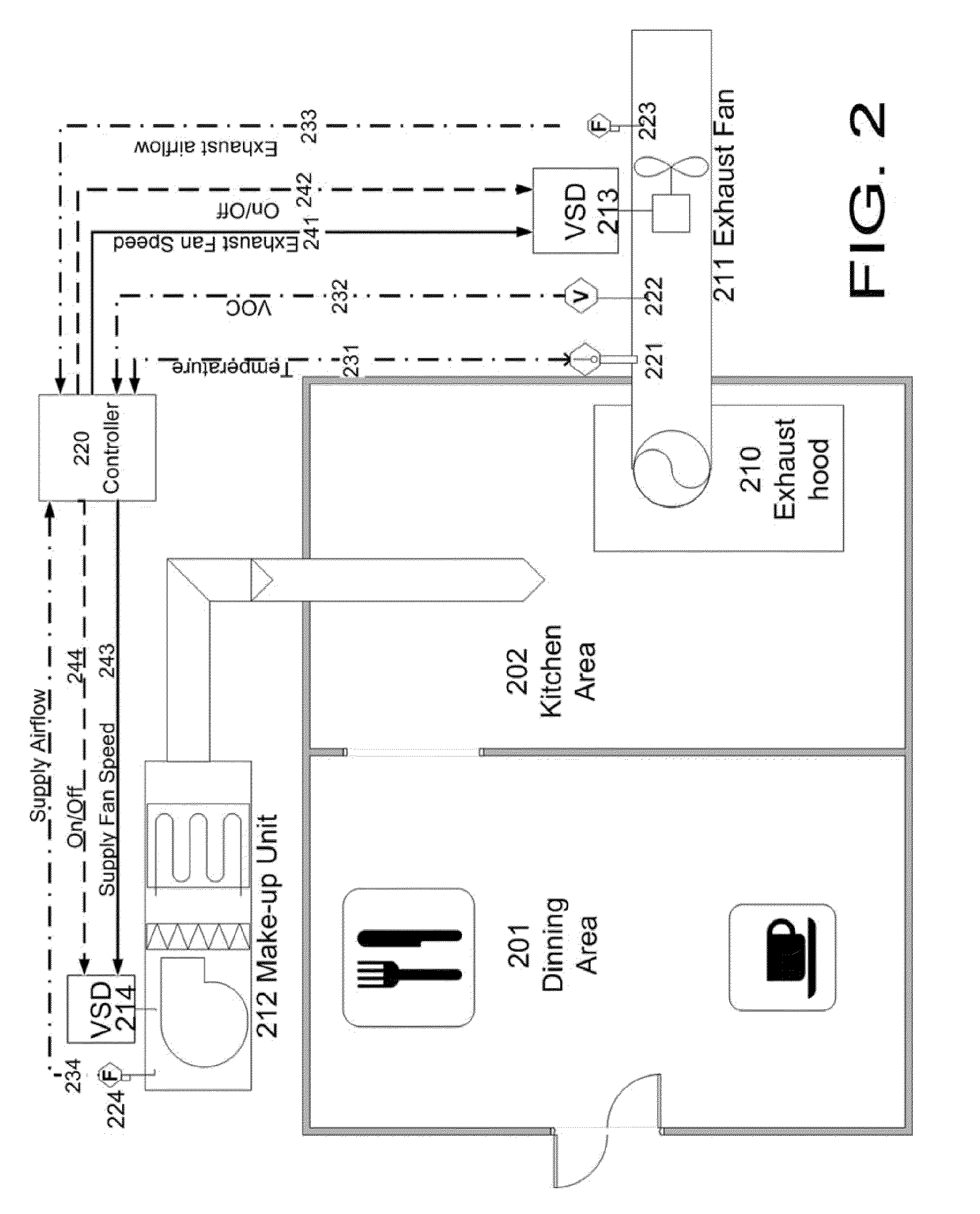
[0022]The present invention uses the Volatile Organic Compound (VOC) gas transmitter devices and the temperature sensors to detect the kitchen hood usage. This invention reduces the cost significantly compared with the laser device and ultrasonic transmitter. And it eliminates the potential laser hazard for the chef and kitchen staff by providing safer detection method. The sensitivity of the VOC sensor can be adjusted based on the actual applications. It's much easier for installation and maintenance compared with prior inventions. In addition, this device can also detect the bad smell and volatile organic gas in the kitchen, which cannot be detected by the laser or ultrasonic devices.
[0023]The exhaust temperature and VOC concentration are controlled by the proportional-integral-derivative (PID) control loop instead of linear control. One PID loop is controlled to maintain the highest hood temperature at set point. Another PID control loop is controlled to maintain the highest hood VOC concentration at the set point. The exhaust fan VSD speed is the higher value of those two PID loops. It is now widely accepted that the PID control methods can provide reliable and optimal control results if control parameters are well-tuned. If there's more than one exhaust hood, the exhaust fan speed can be controlled at the maximum of all PID loops.

Problems solved by technology

In addition, this device can also detect the bad smell and volatile organic gas in the kitchen, which cannot be detected by the laser or ultrasonic devices.

Method used


Image

  • Kitchens exhaust hood and make-up air handling unit optimal speed control system
  • Kitchens exhaust hood and make-up air handling unit optimal speed control system
  • Kitchens exhaust hood and make-up air handling unit optimal speed control system

Examples


Embodiment Construction

[0032]Exemplary Exhaust & Make-Up Control System

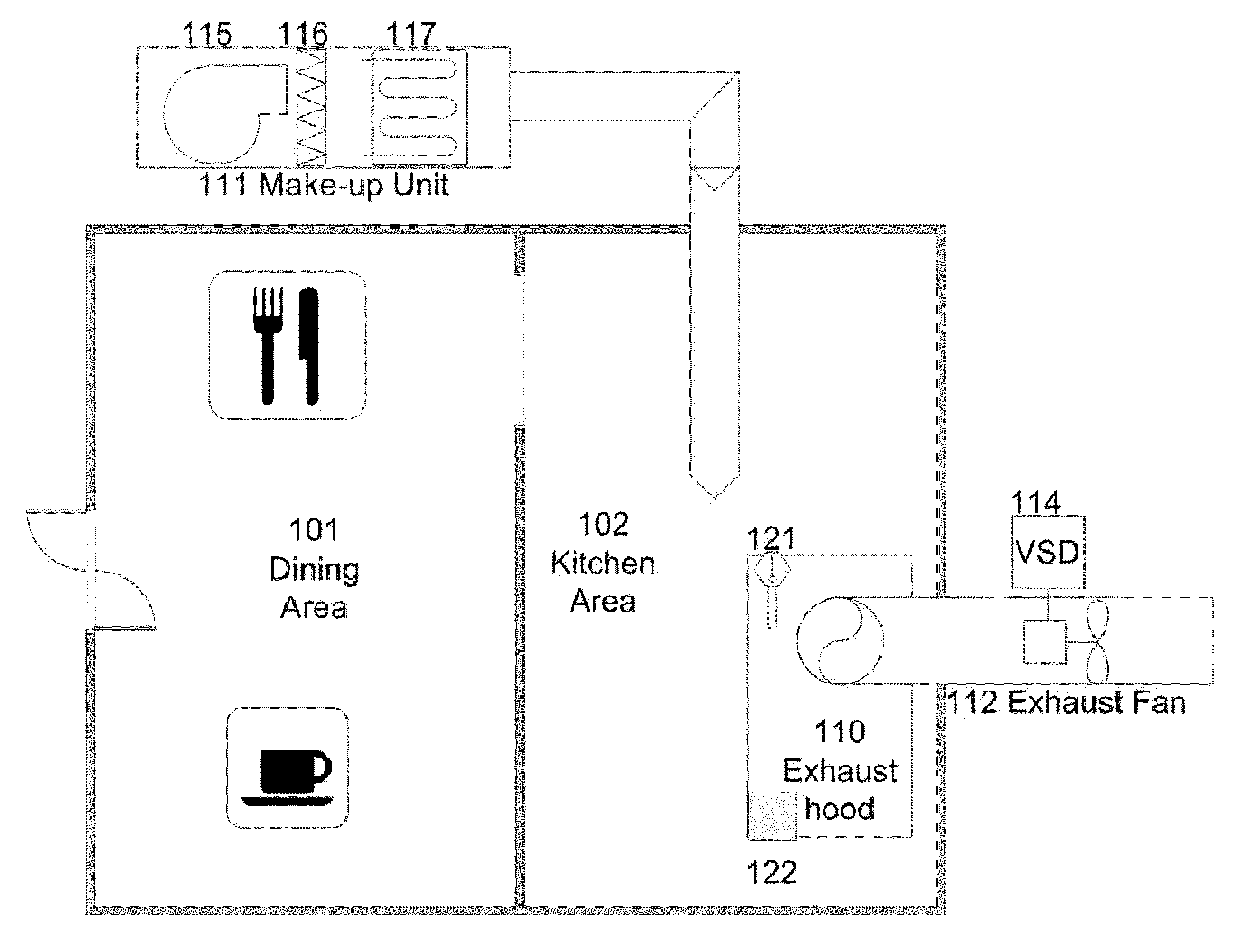
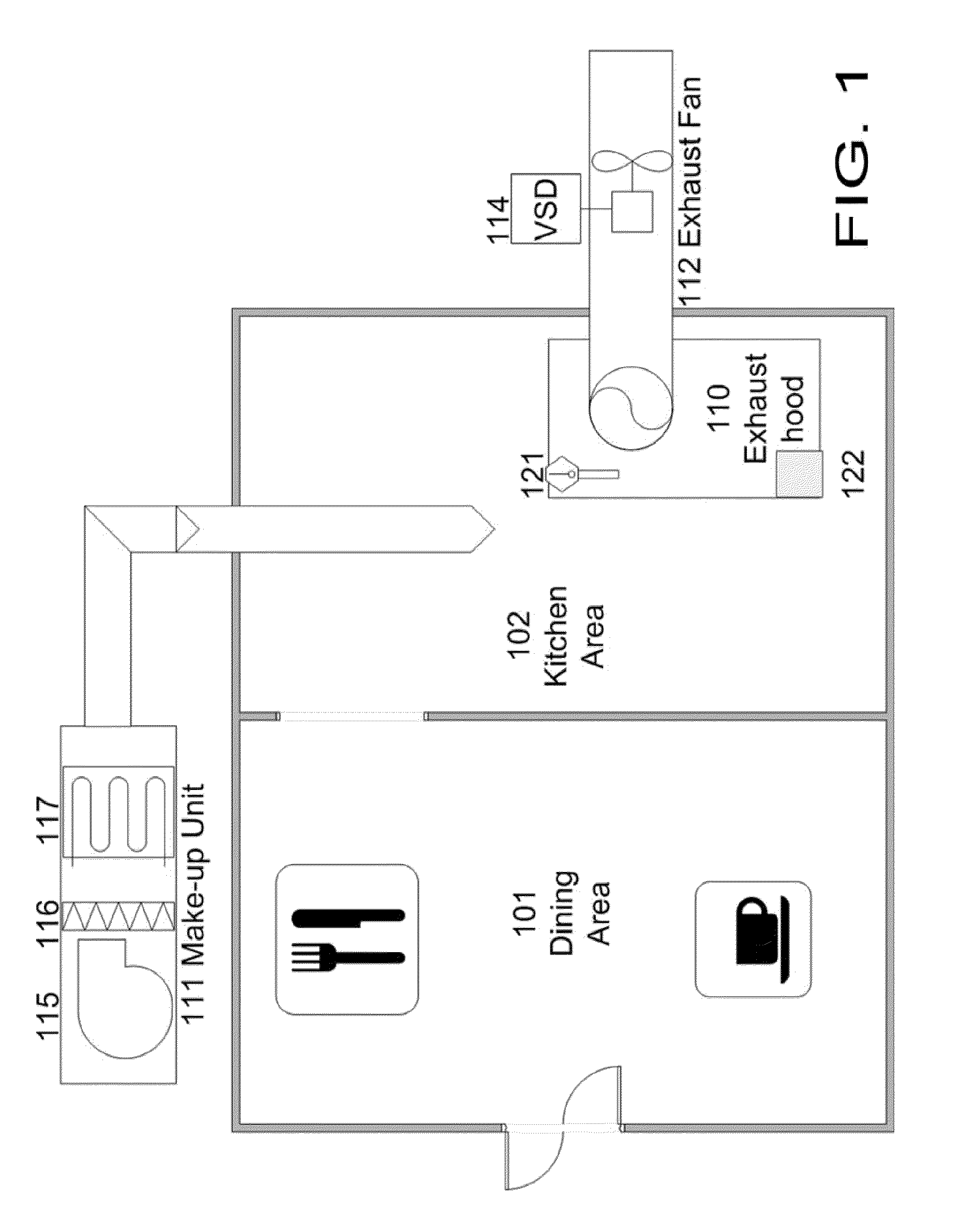
[0033]Referring to FIG. 2, a facility such as a restaurant or institutional facility includes a kitchen area (102) and at least one adjacent room such as a dining room (101) with an interior wall separating the two areas. Kitchen includes a plurality of commercial cooking units such as one or more stoves, ovens, griddles and the like. Facility is also equipped with a HVAC system as at which maintains the inside environment at a suitable condition for the use of the occupants of kitchen.

[0034]Effluents generated by the cooking process include grease in the solid, liquid, and vapor states; smoke particles; and volatile organic compounds (VOCs or low-carbon aromatics, commonly referred to as odors). Effluent controls in the vast majority of today's kitchen ventilation systems are limited to the removal of solid and liquid grease particles by grease removal devices located in the hood. One of the most common methods of cooking effluent con...


PUM


Abstract

Disclosed is a kitchen exhaust hood and makeup unit control system comprising a control device for controlling the variable speed drive (VSD) for the associated fan, and measurement devices comprising Volatile Organic Compound (VOC) gas transmitter devices and temperature transmitters devices. The exhaust fan VSD speed is controlled to maintain the kitchen hood area at certain comfort level (indoor air quality and thermal comfort) by monitoring the VOC concentration and exhaust duct temperature. The air quality sensors measure the concentration of multiple gases and odorous substances in the air with constant output. These substances, for example, may be cooking smoke, kitchen vapors, human odors and unpleasant smells. The exhaust fan speed is controlled using the proportional-integral-derivative (PID) control loop. The kitchen exhaust and make-up unit supply airflow rate may be measured by an airflow measurement means such as Fan Airflow Station. The kitchen make-up unit fan speed is controlled to maintain the constant airflow difference between the exhaust air and make-up air to maintain the slightly negative pressure in the kitchen area.

Description

CROSS-REFERENCES TO RELATED APPLICATIONS[0001]U.S. Patent Documents3,723,746March 1973Lawson et al.3,743,430July 1973Riggs3,809,480May 1974Somerville et al.3,932,137January 1976Culpepper, Jr.4,781,460November 1988Bott4,903,685February 1990Melink4,980,571December 1990McRae et al.5,074,281December 1991Fluhrer et al.5,146,284September 1992Tabarelli et al.5,693,949December 1997Paris5,882,254March 1999Jacob6,037,580March 2000Renk6,078,040June 2000Endo et al.6,170,480January 2001Melink et al.6,198,110March 2001Kaye et al.6,583,726June 2003Johnson et al.6,822,216November 2004Lang et al.2004 / 0090627May 2004Hinderling2006 / 0032492February 2006Bagwell et al.7,048,199Jan. 20, 2004Melink et al.7,442,119Apr. 18, 2007Fluhrer; HenryForeign Patent Documents[0002]4,418,409August, 1995DE19 / 509,612March, 1996DE200 21 349April, 2001DE201 21 682March, 2003DE0603538June, 1994EP0 788 082October, 2002EP06 / 281,219October, 1994JPBACKGROUND OF THE INVENTION[0003]I. Field of the Invention[0004]The present inven...

Claims


Application Information

Patent Timeline
IPC IPC(8): G05D7/00F24C15/20
CPCF24C15/2021G05D27/02G05D23/19G05D21/02
Inventor LIU, GUOPENG
Owner LIU MINGSHENG
Learn More