Organic light-emitting device having improved light-emitting efficiency and method for fabricating the same

a light-emitting device and organic technology, applied in the direction of electroluminescent light sources, thermoelectric devices, electric lighting sources, etc., can solve the problems of reducing the intensity of light having the remaining wavelength, the small aperture ratio negatively affecting the consumption of driving power and a life span of the oled, so as to achieve the effect of improving the light-emitting efficiency of the organic light-

Active Publication Date: 2010-12-23
LG DISPLAY CO LTD
View PDF12 Cites 38 Cited by
  • Summary
  • Abstract
  • Description
  • Claims
  • Application Information

AI Technical Summary

Benefits of technology

[0015]According to the present invention, in an organic light emitting device, a layer having a refractive index in the range of 1.3 to 3 is further formed on an upper electrode of at least one region of regions through which rays having red, green, and blue colors are passed. Thereby, an optical length regarding the microcavity effect can be easily controlled, and thus, the light emitting efficiency of the organic light emitting device can be easily improved.

Problems solved by technology

The above-mentioned problems are serious in the case of when a sophisticated display requiring a large number of TFTs is manufactured.
This small aperture ratio negatively affects the consumption of driving power and a life span of the OLED.
Accordingly, the destructive interference and the constructive interference of light occur, causing a phenomenon where only light having a predetermined wavelength is maintained and the intensity of light having the remaining wavelength is reduced.
However, when the thickness of the lower electrode is controlled according to the type of color of emitted light by using masks, the type of which depends on the type of color of emitted light, during a typical sputtering process in the course of forming the lower electrode, there are problems in that a life span of the mask is reduced and alien substances are generated during the process.
In addition, an uneven structure that is caused by a nonuniform thickness of the lower part of light emitting layer according to the type of color of emitted light may reduce the stability of the whole manufacturing process of the device.
In this case, there are problems in that it is difficult to perform the process and driving voltage is increased.

Method used


Image

  • Organic light-emitting device having improved light-emitting efficiency and method for fabricating the same
  • Organic light-emitting device having improved light-emitting efficiency and method for fabricating the same
  • Organic light-emitting device having improved light-emitting efficiency and method for fabricating the same

Examples


Embodiment Construction

[0019]Hereinafter, the present invention will be described in detail.

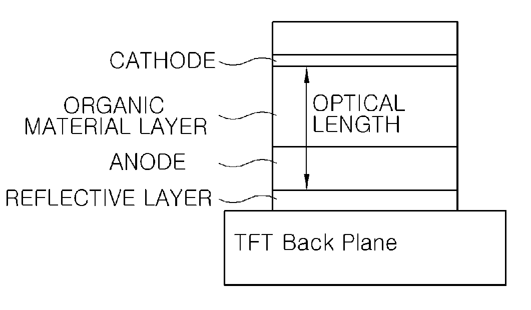
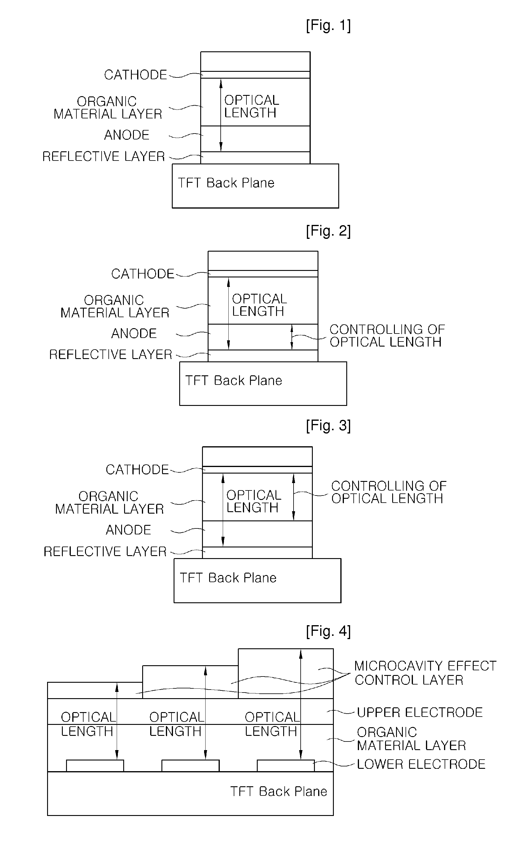
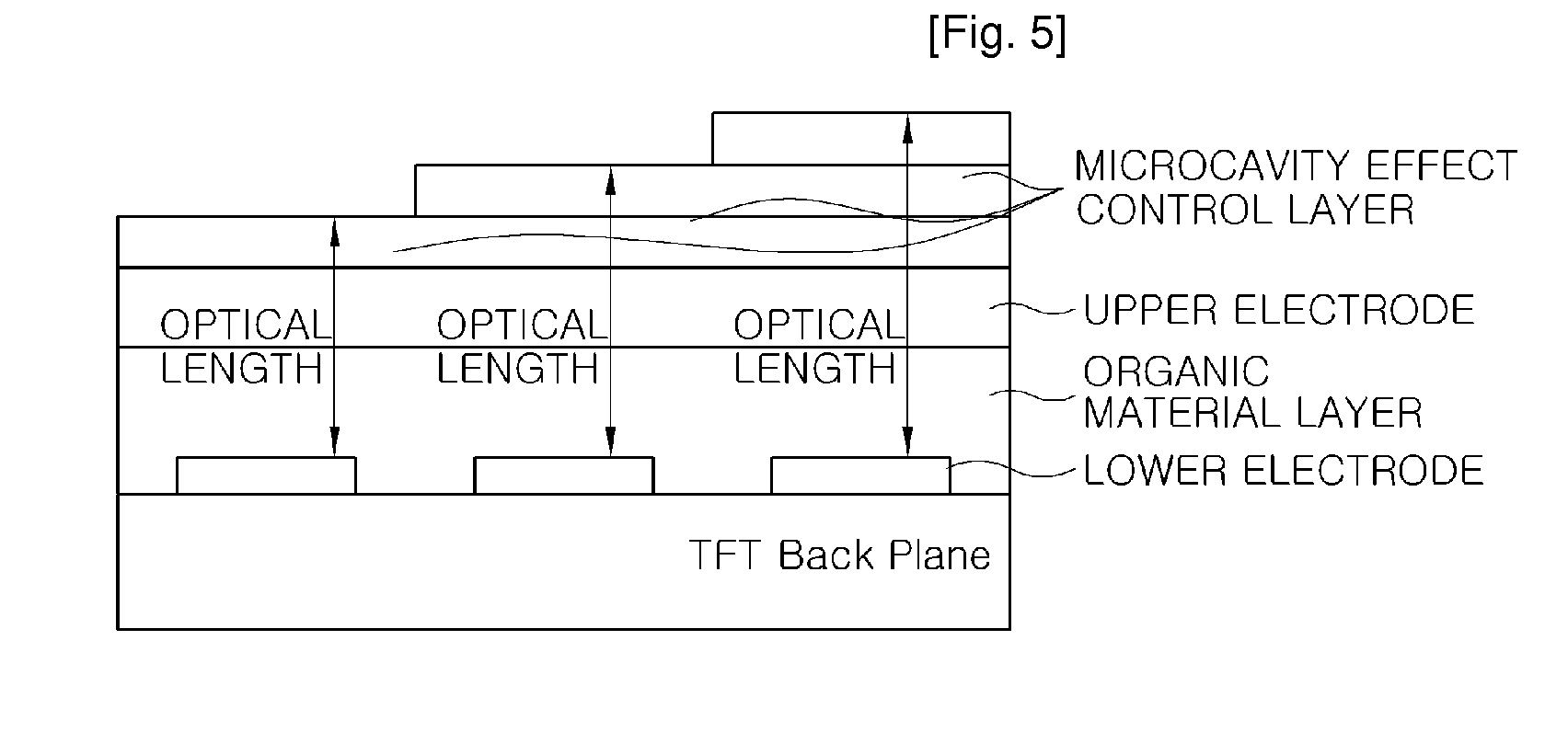
[0020]In an organic light emitting device according to the present invention, in the case of when an upper electrode having the transmittance of 80% or more is used in respects to light that is emitted from a light emitting layer of the device, the microcavity effect may be obtained due to a difference between the refractive index of the upper electrode and the refractive index of an air layer. In this case, an upper limit of an optical length regarding the microcavity effect is an interface of the upper electrode and the air layer. Unlike this, in a known art, the upper electrode that has the low transmittance in respects to light and acts as the reflective layer is used as the above upper electrode. Thus, the upper limit of the optical length regarding the microcavity effect is the interface of the upper electrode and the organic material layer.

[0021]Due to a difference between the present invention and the above...


PUM


Abstract

The present invention provides an organic light emitting device in which a layer having a refractive index in the range of 1.3 to 3 is further formed on an upper electrode of at least one region of regions through which rays having red, green, and blue colors are passed and a method of manufacturing the organic light emitting device. An optical length that can cause the microcavity effect according to the type of color of emitted light is controlled by using the layer to manufacture the organic light emitting device having high light emitting efficiency.

Description

TECHNICAL FIELD[0001]The present invention relates to an organic light emitting device and a method of manufacturing the same. More particularly, the present invention pertains to an organic light emitting device in which an optical length regarding the microcavity effect is easily controlled, and a method of manufacturing the same. This application claims priority from Korea Patent Application No. 10-2007-0011512 filed on Feb. 5, 2007 in the KIPO, the disclosure of which is incorporated herein by reference in its entirety.BACKGROUND ART[0002]Various types of organic light emitting devices are known in the known art, and may be used for different purposes. The organic light emitting device is classified into a top light emitting type organic light emitting device, a bottom light emitting type organic light emitting device, and a dual-sided light emitting type organic light emitting device. If the bottom light emitting type organic light emitting device is used in an active matrix di...

Claims


Application Information

Patent Timeline
Patent Type & Authority Applications(United States)
IPC IPC(8): H01L51/50H01L33/00
CPCH01L27/3211H05B33/10H01L51/5265H10K59/35H10K50/852H05B33/22H05B33/14H05B33/26
Inventor KANG, MIN-SOONOH, JEOUNG-KWENHAHM, YUN HYEKIM, JUNG-BUMKIM, JONG-SEOKLEE, JUNG-HYOUNG
Owner LG DISPLAY CO LTD
Why Eureka
Try Eureka