Dielectric antenna

Active Publication Date: 2010-12-23
KROHNE MESSTECHNICK GMBH & CO KG
View PDF4 Cites 6 Cited by
  • Summary
  • Abstract
  • Description
  • Claims
  • Application Information

AI Technical Summary

Benefits of technology

[0018]On the one hand, in this way, very good encapsulation of the antenna is implemented altogether so that the dielectric antenna is also suitable for applications which have especially high demands with respect to attainable hygiene, such as, for example, applications in the food industry. Because the lens surrounds the electromagnetic feed element and the hollow conductor, the number of intermediate spaces and transition sites between the lens and electromagnetic feed element is minimized.
[0019]On the other hand, due to the shape of the dielectric lens an

Problems solved by technology

However, these requirements are contradictory with respect to the mechanical measures which must be conventionally taken for their technical implementation.
So that the aperture is also used for purposes of a narrow direction of maximum radiation, the electromagnetic radiation emitted from the transmission region of the lens must have a phase front as planar as possible, and this planar phase front can be implemented more easily with increasing length of the antenna; likewise, this opposes the desired compact type of construction.
Known dielectric antennas, in addition to difficult simultaneous implementation of a narrow direction of maximum radiation with a simultaneously compact type of construction, have a further disadvantage which is related to the mutual arrangement of the electromagnetic feed element and the lens made of dielectric material.
The two aforementioned ve

Method used


Image

  • Dielectric antenna
  • Dielectric antenna
  • Dielectric antenna

Examples


Embodiment Construction

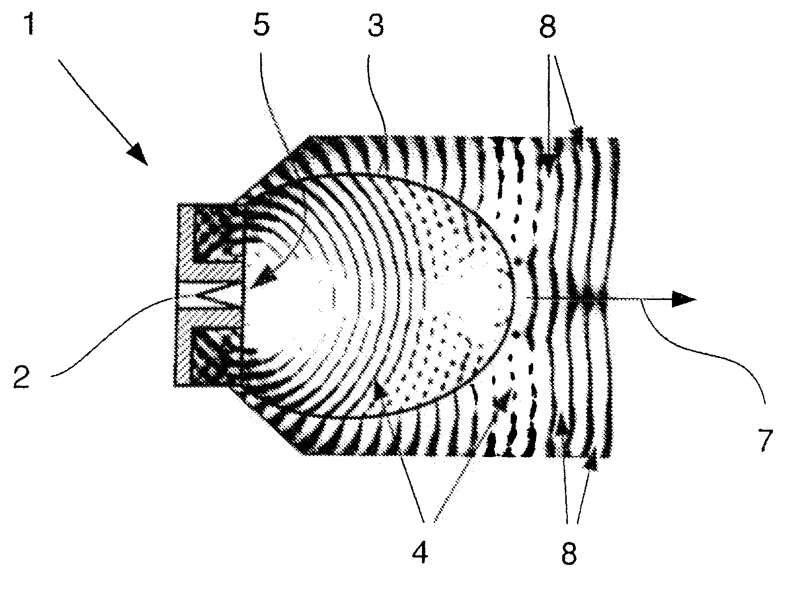
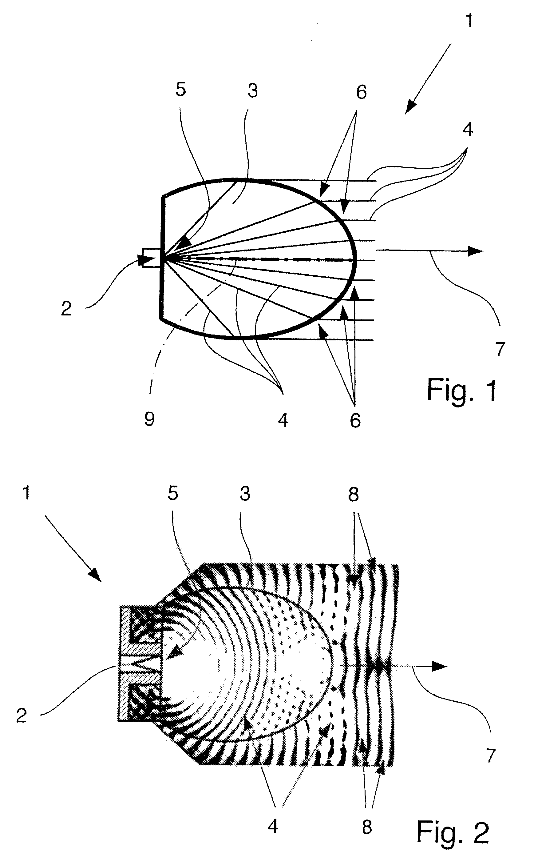
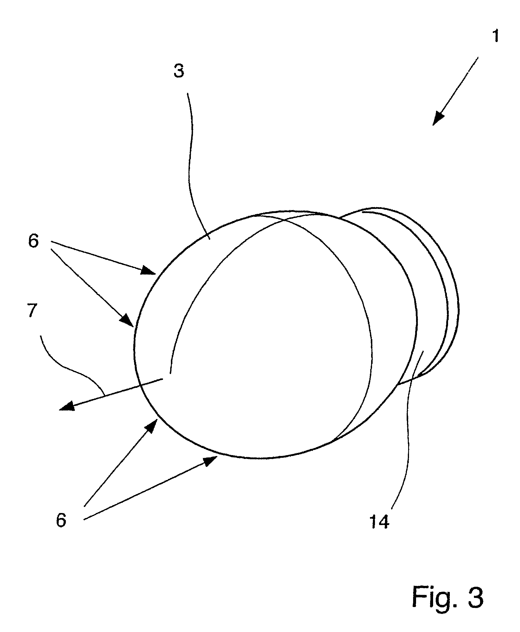
[0032]FIGS. 1 to 7 show a dielectric antenna 1 with an electromagnetic feed element 2 and with a lens 3 made of a dielectric material. The manner of operation of the antenna 1 is always based on the feed element 2 emitting electromagnetic radiation 4 and the lens 3 being supplied with electromagnetic radiation 4 in the feed region 5, the lens 3 relaying the electromagnetic radiation 4 and emitting it with the transmission region 6 of the lens.

[0033]In all figures it is shown that the lens 3 is shaped ellipsoidally at least in the transmission region 6 and the lens 3 is arranged relative to the feed element 2 such that the electromagnetic radiation 4 emitted from the lens 3 in the direction of maximum radiation 7 of the antenna 1 has an essentially planar phase front 8, the phase front 8 being explicitly recognizable only in FIG. 2.

[0034]FIG. 1 clearly shows how the electromagnetic radiation 4 which has been emitted from the schematically shown feed element 2 propagates within the le...


PUM


Abstract

A dielectric antenna with an electromagnetic feed element (2) and with a lens (3) made of a dielectric material, the feed element (2) emitting electromagnetic radiation (4) and the lens (3) being supplied with electromagnetic radiation (4) in the feed region (5), the lens (3) relaying the electromagnetic radiation (4) and radiating it with the transmission region (6). To configure these dielectric antennas such that the disadvantages of the dielectric antennas known from the prior art are at least partially avoided, first of all, the lens (3) is shaped essentially ellipsoidally at least in the transmission region (6) and the lens (3) is arranged relative to the feed element (2) such that the electromagnetic radiation (4) emitted by the lens (3) in the direction of maximum radiation (7) of the antenna has an essentially planar phase front.

Description

BACKGROUND OF THE INVENTION[0001]1. Field of the Invention[0002]The invention relates to a dielectric antenna with an electromagnetic feed element and with a lens made of a dielectric material, the feed element emitting electromagnetic radiation and the lens in the feed region being supplied with electromagnetic radiation, the lens relaying the electromagnetic radiation and emitting it with the transmission region.[0003]2. Description of Related Art[0004]Dielectric antennas are known from various fields of engineering in quite varied types of construction. However, it is common to dielectric antennas that dielectric materials, especially those dielectric materials which have especially low losses, are used to guide and radiate electromagnetic waves. For example, using polytetraflouroethylene or polypropylene as the dielectric material or other dielectrics with low permittivity for the lens is known.[0005]In industrial process engineering, dielectric antennas are often used, for exam...

Claims


Application Information

Patent Timeline
IPC IPC(8): H01Q19/08
CPCH01Q13/06H01Q19/09H01Q15/08
Inventor POHL, NILS
Owner KROHNE MESSTECHNICK GMBH & CO KG
Why Eureka
Try Eureka