Apparatus and method for imaging subsurface structure of target area by using waveform inversion

a technology of target area and waveform, applied in the field of subsurface exploration technology, can solve the problems of distortion of gradient direction, many obstacles in exploration,

Active Publication Date: 2010-12-23
SEOUL NAT UNIV R&DB FOUND
View PDF4 Cites 26 Cited by
  • Summary
  • Abstract
  • Description
  • Claims
  • Application Information

AI Technical Summary

Benefits of technology

[0013]The following description relates to an apparatus and method for imaging the subsurface structure of a target area by using waveform inversion in the frequency domain or by using waveform inversion in the Laplace domain or the Laplace-Fourier domain, which can efficiently utilize insufficient low-frequency components of data obtained through actual field exploration, in order to obtain a velocity model close to the actual subsurface structure of the target area. In particular, the following description relates to an apparatus and method for imaging the subsurface structure of a target area, the apparatus and method capable of equally distributing all frequency components, all Laplace damping constants, or all Laplace-Fourier damping constants in the determination of the direction of a gradient vector and capable of determining a step length without requiring an additional operation such as a line search.

Problems solved by technology

However, real seismic data obtained through actual field exploration presents many obstacles to waveform inversion: the absence of low-frequency data, two-dimensional (2D) acoustic approximations of three-dimensional (3D) real earth wave propagation, and source-receiver coupling to the earth.
Noise is perhaps the most important of these obstacles because ambient background vibrations always contaminate real seismic data.
Consequently, this can result in the distortion of the gradient direction.

Method used


Image

  • Apparatus and method for imaging subsurface structure of target area by using waveform inversion
  • Apparatus and method for imaging subsurface structure of target area by using waveform inversion
  • Apparatus and method for imaging subsurface structure of target area by using waveform inversion

Examples


Embodiment Construction

[0032]The invention is described more fully hereinafter with reference to the accompanying drawings, in which exemplary embodiments of the invention are shown. Descriptions of well-known functions and constructions are omitted to increase clarity and conciseness. Also, the terms used in the following description are terms defined taking into consideration the functions obtained in accordance with the present invention, and may be changed in accordance with the option of a user or operator or a usual practice. Therefore, the definitions of these terms should be determined based on the entire content of this specification.

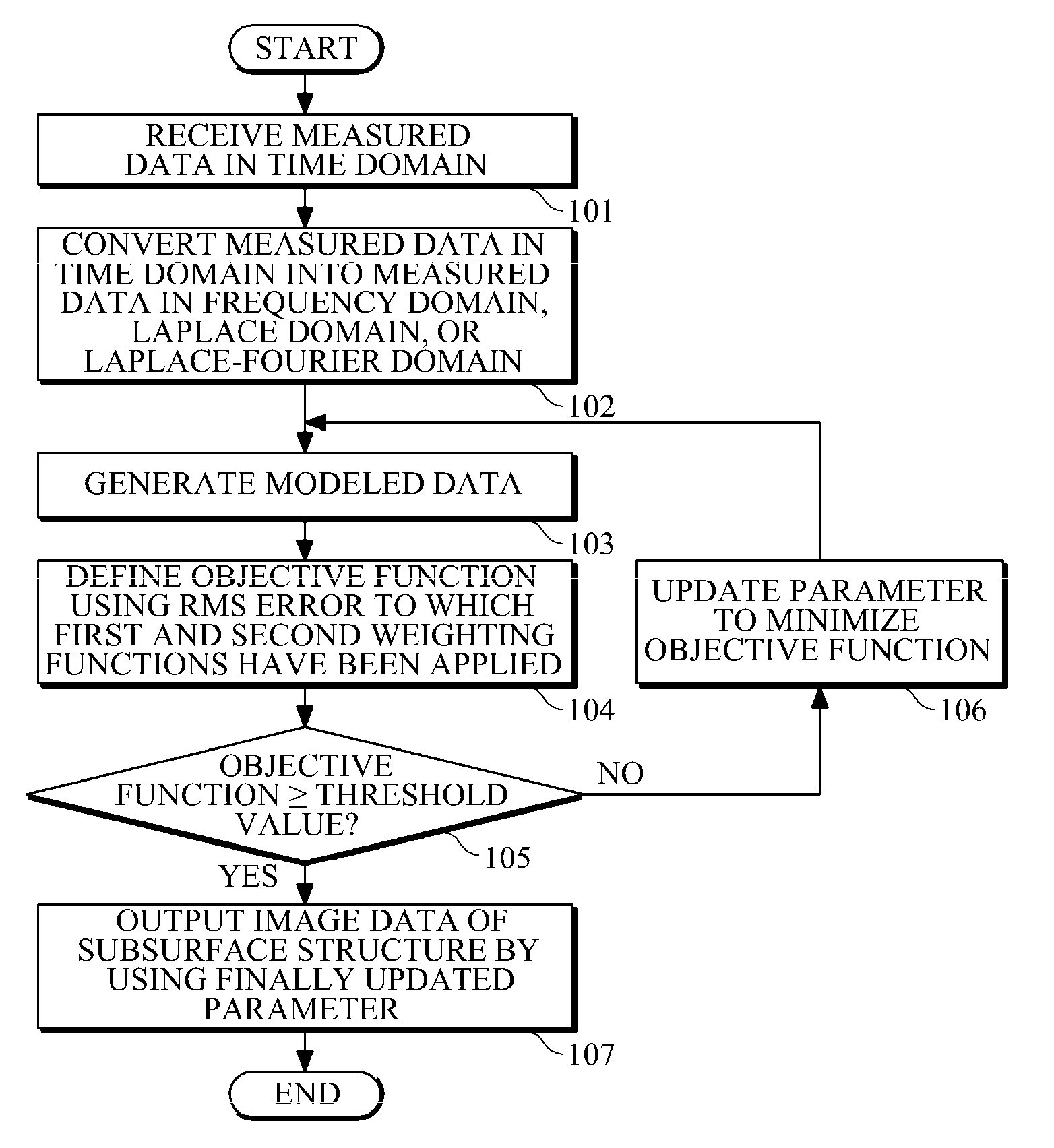
[0033]‘Waveform inversion’ according to an embodiment of the present invention refers to the process of reconstructing information about the subsurface structure of a target area (e.g., a velocity or density model of the target area) from measured data obtained through actual field exploration. Waveform inversion may involve a modeling process in which an analyzer se...


PUM


Abstract

Provided are an apparatus and method for imaging the subsurface structure of a target area by using waveform inversion. In the apparatus and method, the subsurface structure of a target area is estimated using waveform inversion of a seismic signal in the frequency domain, the Laplace domain, or the Laplace-Fourier domain, and an objective function is defined by applying a weighting function such that the objective function makes a different contribution for each frequency, each Laplace damping constant, or each Laplace-Fourier damping constant. The objective function is not limited to a particular type of objective function and a weighting function can be automatically determined when a gradient vector for each frequency, each Laplace damping constant, or each Laplace-Fourier damping constant is normalized. In addition, a gradient direction for all frequencies can be defined by applying another weighting function to the sum of respective gradient vectors for all frequencies, all Laplace damping constants, or all Laplace-Fourier damping constants, wherein the weighting function can also be automatically determined by normalization.

Description

CROSS-REFERENCE TO RELATED APPLICATION[0001]This application claims the benefit under 35 U.S.C. §119(a) of a Korean Patent Application No. 10-2009-0054071, filed on Jun. 17, 2009, the entire disclosure of which is incorporated herein by reference for all purposes.BACKGROUND[0002]1. Field[0003]The following description relates to subsurface exploration technology, and more particularly, to a technology of imaging the subsurface structure of a target area by using waveform inversion in a frequency domain, Laplace domain, or a Laplace-Fourier domain.[0004]2. Description of the Related Art[0005]Subsurface exploration is used to identify the subsurface structure and geological characteristics of a specified area and, particularly, to find useful resources (such as oil) buried underground. As the use of underground resources increases, subsurface exploration is widely being conducted not only in land but also in the sea. Subsurface exploration in land or sea plays a crucial role in discov...

Claims


Application Information

Patent Timeline
Patent Type & Authority Applications(United States)
IPC IPC(8): G01V1/36
CPCG01V1/303G01V1/32G01V1/28G01V1/30
Inventor SHIN, CHANG-SOO
Owner SEOUL NAT UNIV R&DB FOUND
Why Eureka
Try Eureka