Focus control circuit for adjusting the focus by moving a lens

a control circuit and lens technology, applied in the direction of camera focusing arrangement, printers, instruments, etc., can solve the problem of taking a long time to complete a search, and achieve the effect of less cost and maximum contrast of a subj

Active Publication Date: 2010-12-23
SEMICON COMPONENTS IND LLC
View PDF10 Cites 22 Cited by
  • Summary
  • Abstract
  • Description
  • Claims
  • Application Information

AI Technical Summary

Benefits of technology

[0006]The contrast detecting method can be achieved with less cost than an active method in which the subject is irradiated with infrared rays or ultrasonic waves and the distance to the subject is measured based on the reflected waves. Nevertheless, the contrast method has a drawback in that it takes some time to complete a search for the lens position in which the contrast of a subject is maximized. It is desired that the processing of focusing the subject be completed within one second after a user has pressed a shutter button halfway.

Problems solved by technology

Nevertheless, the contrast method has a drawback in that it takes some time to complete a search for the lens position in which the contrast of a subject is maximized.

Method used


Image

  • Focus control circuit for adjusting the focus by moving a lens
  • Focus control circuit for adjusting the focus by moving a lens
  • Focus control circuit for adjusting the focus by moving a lens

Examples


first embodiment

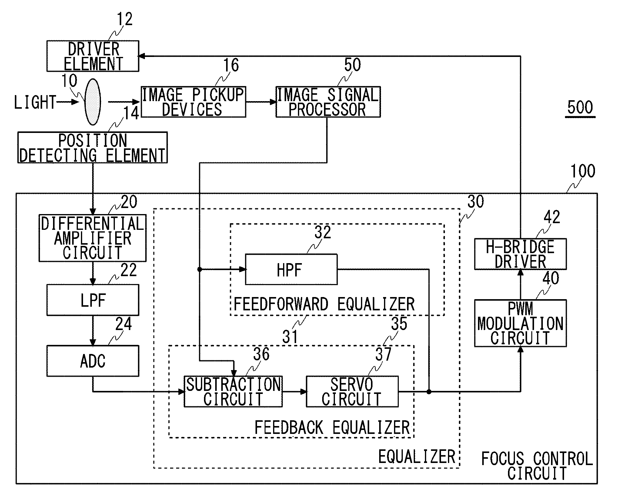
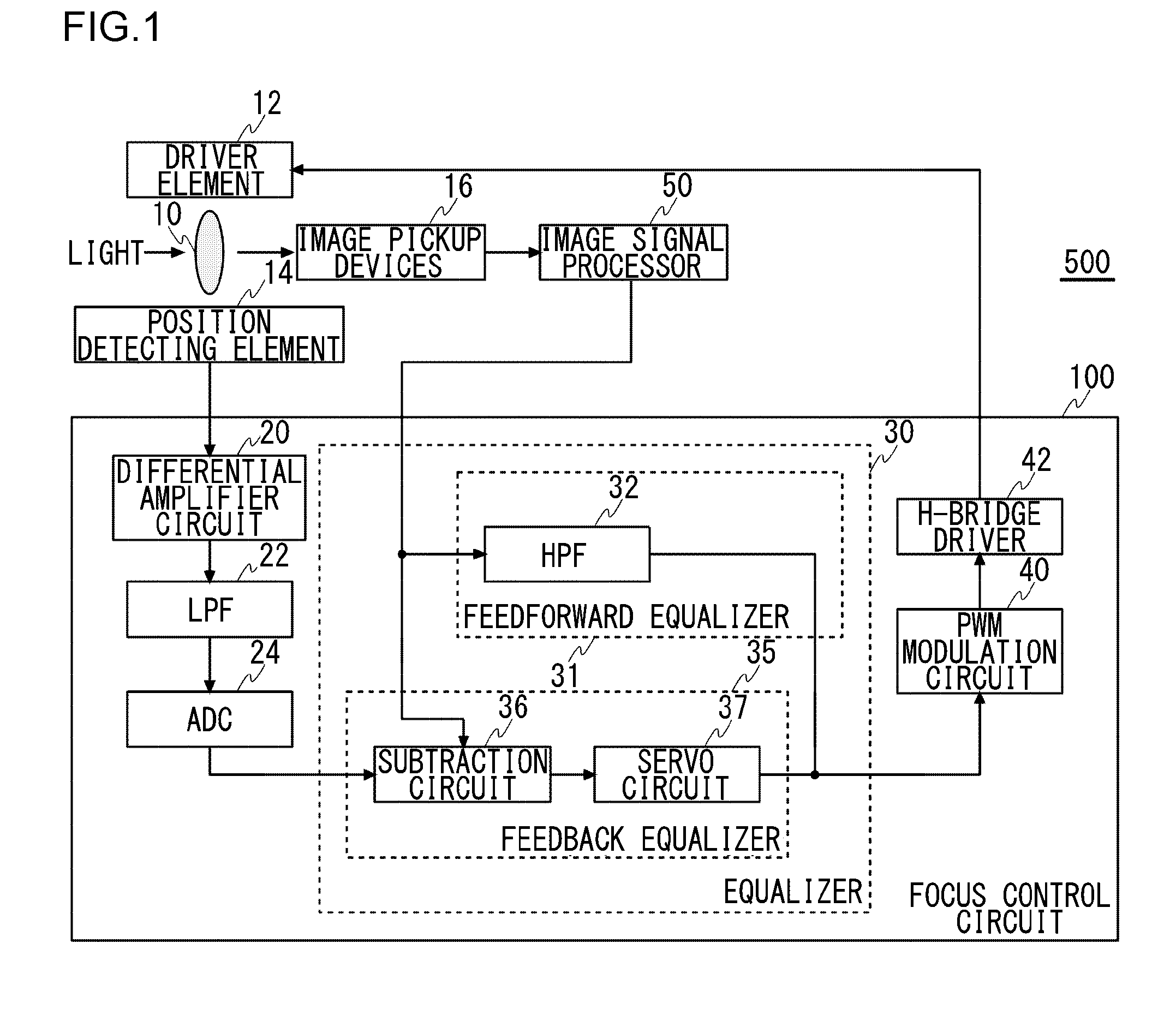
[0016]FIG. 1 illustrates a structure of an image pickup apparatus 500 provided with a focus control circuit 100 according to the present invention. The image pickup apparatus 500 includes a lens 10, a driver element 12, a position detecting element 14, image pickup devices 16, an image signal processor (ISP) 50, and a focus control circuit 100. Other structural components, such as an image coding engine and a recording medium, which are not involved in the auto-focus control are omitted in FIG. 1.

[0017]The image pickup devices 16 convert the light signals transmitted through the lens 10, which is an optical component, into electric signals and outputs the electric signals to the image signal processor 50. The image pickup devices 16 may be CCD (charge-coupled device) sensors or CMOS (complementary metal-oxide semiconductor) image sensors.

[0018]The driver element 12, which is an element used to adjust the position of the lens 10, moves the lens 10 along an optical direction in respon...

second embodiment

[0040]In the second embodiment, the hall element 14a is driven by a constant current. In other words, the operational amplifier that constituting the differential amplifier circuit 62 keeps the voltage applied across the input terminals of the hall element 14a constant and thereby performs a control such that a bias current, which is a constant current, can flow through the hall element 14a.

[0041]A noninverting input terminal of the operational amplifier that constitutes the differential amplifier circuit 62 is connected to the DAC circuit 61, whereas an inverting input terminal of this operational amplifier is connected to the second input terminal of the hall element 14a. The output terminal of this operational amplifier is connected to the first input terminal of the hall element 14a. The noninverting input terminal of this operational amplifier receives a gain adjustment value from the DAC circuit 61. This operational amplifier amplifies the difference between the gain adjustme...


PUM


Abstract

A focus control circuit is installed in an image pickup apparatus including a lens, a driver element for adjusting the position of the lens, and a position detecting element for detecting the position of the lens. A feedback equalizer included in the focus control circuit generates a drive signal used to adjust the position of the lens to a target position, based on a difference between the position of the lens identified by the output signal of the position detecting element and the target position of the lens set externally, and controls the driver element.

Description

CROSS-REFERENCE TO RELATED APPLICATIONS[0001]This application is based upon and claims the benefit of priority from the prior Japanese Patent Applications No. 2009-145363, filed on Jun. 18, 2009, and Japanese Patent Applications No. 2009-145364, filed on Jun. 18, 2009, the entire contents of which are incorporated herein by reference.BACKGROUND OF THE INVENTION[0002]1. Field of the Invention[0003]The present invention relates to a focus control circuit for determining the focus position by actively moving a lens.[0004]2. Description of the Related Art[0005]Most of camera modules installed in commonly-used digital cameras and mobile phones are provided with auto-focusing functions. A contrast detecting method is often used as the auto-focusing function employed in such a compact-size camera. In the contrast detecting method, a lens position in which the contrast of a subject lying in a picked-up image frame is maximized is detected by actively moving the lens and then the lens is mov...

Claims


Application Information

Patent Timeline
Patent Type & Authority Applications(United States)
IPC IPC(8): G03B3/10G02B7/28G03B13/36G03B30/00
CPCG02B7/38H04N5/23212G03B3/10H04N23/675G02B7/09G03B13/36G03B2205/0053
Inventor TSUDA, HIROYUKIKURA, TAKESHI
Owner SEMICON COMPONENTS IND LLC
Why Eureka
Try Eureka