Drilling Tool

a drilling tool and drill bit technology, applied in the direction of cutting inserts, twisting drills, manufacturing tools, etc., can solve the problems of cost advantages that cannot be considered

Active Publication Date: 2010-12-23
KENNAMETAL INC
View PDF7 Cites 12 Cited by
  • Summary
  • Abstract
  • Description
  • Claims
  • Application Information

AI Technical Summary

Benefits of technology

[0009]In a further configuration, those side walls of the cutting insert body forming the indexable insert that are defined at the margin by the secondary cutting edges are configured in such a way that a section of the side wall tapers in the direction of the respective secondary cutting edge. When the tool is rotating, this tapering produces a clearance for the tool. In this way, it i

Problems solved by technology

This results in consid

Method used


Image

  • Drilling Tool
  • Drilling Tool
  • Drilling Tool

Examples


Embodiment Construction

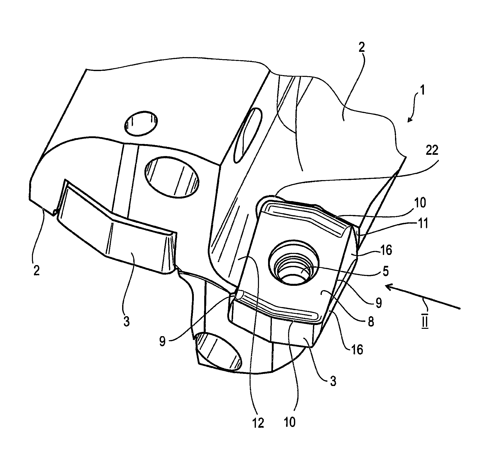
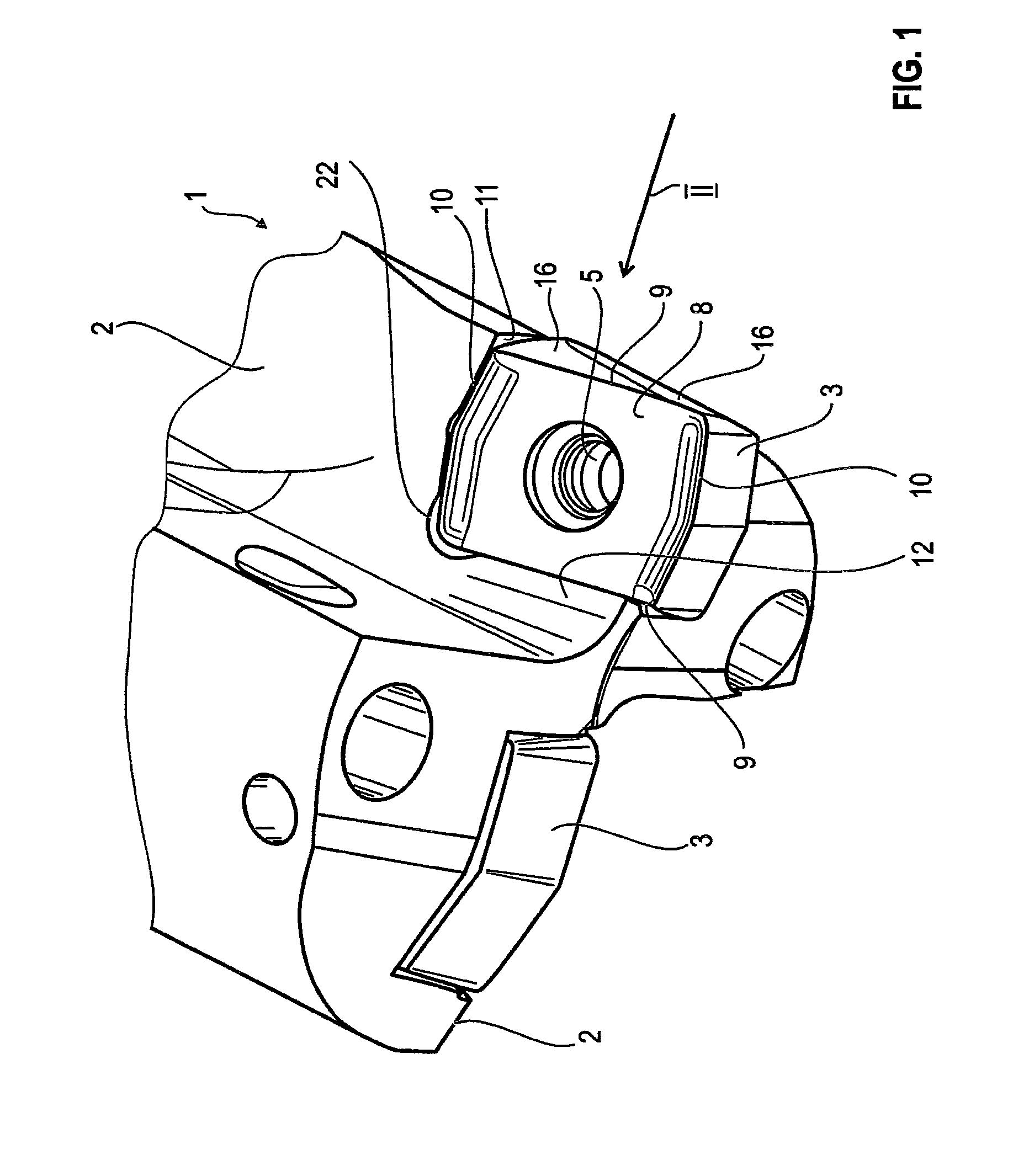
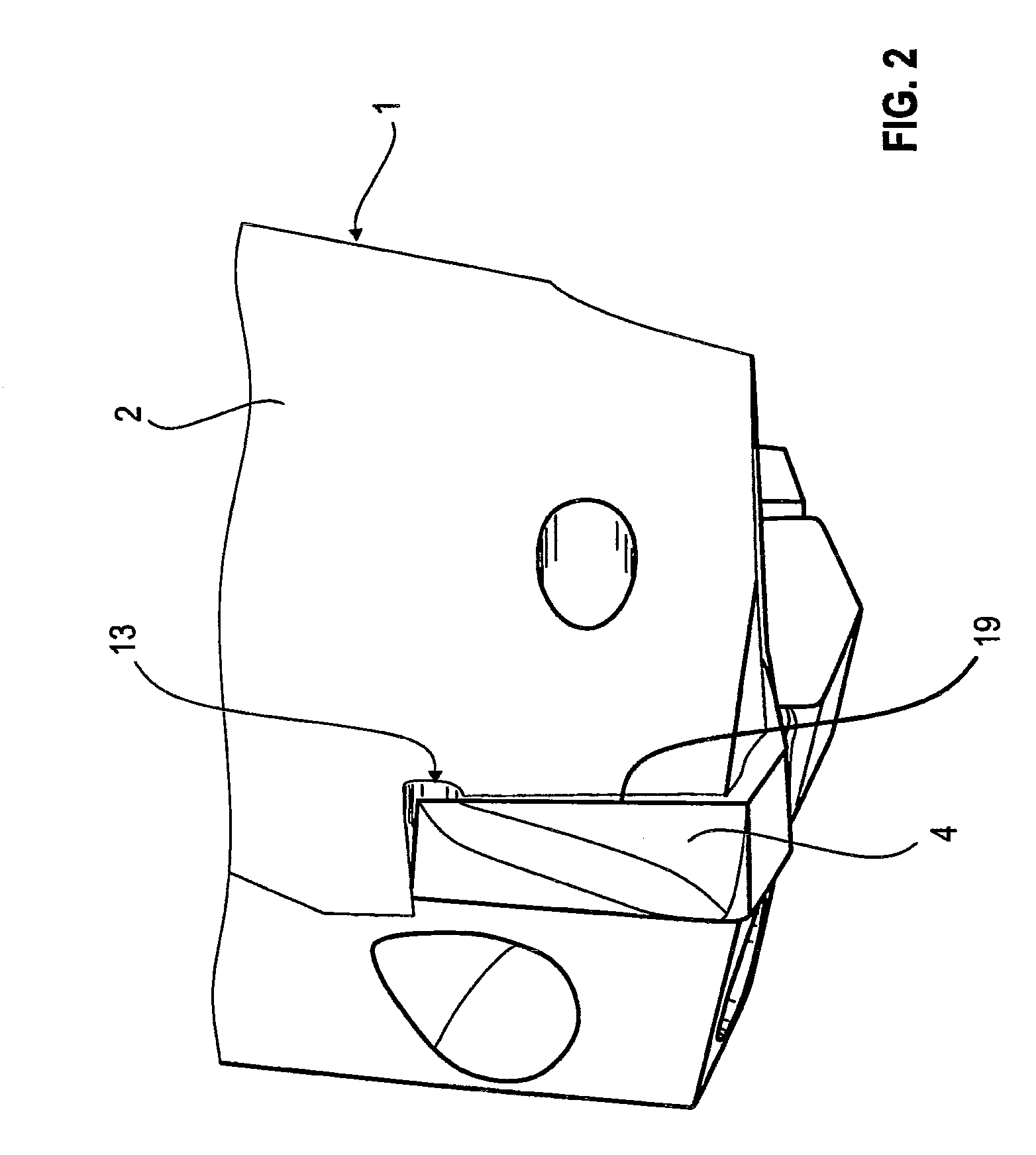
[0016]The drilling tool 1 has two flutes 2 in the exemplary embodiment. A respective indexable insert 3 is held in an insert seat 4 at the end (shown in FIG. 1) of the two flutes 2.

[0017]A fixing hole 5 passes centrally through the indexable insert 3. In the final fitted state, a screw or the like passes through the fixing hole 5 in order to effectively fix the indexable insert 3 on the drilling tool 1.

[0018]The body of the indexable insert 3 has two opposite long side walls 6 and two likewise opposite short side walls 7. The side walls 6, 7 are in each case defined by the two flat planes formed as rake faces 8. Portions of the secondary cutting edges 9 and of the main cutting edges 10 are formed in each case in the region between the side walls 6, 7 and the rake faces 8. In the exemplary embodiment shown in FIG. 1, the right-hand secondary cutting edge 9 is the active secondary cutting edge and the main cutting edge 10 facing away from the flute 2 is the active main cutting edge. T...


PUM

PropertyMeasurementUnit
Areaaaaaaaaaaa
Distanceaaaaaaaaaa

Abstract

The invention discloses a drilling toll having at least one chip groove for chip removal, having an insert seat which is formed at the end of the chip groove and serves as a holder for an indexable insert with at least one main cutting edge on the two narrow sides and with at least one secondary cutting edge on the two longitudinal sides of one face side wherein the indexable insert has two face sides facing away from one another and bears with its inactive face side on a holding surface of the insert seat, and a partial region of the inactive secondary cutting edge of its active face side lies in the insert seat at a distance from the adjoining side wall of the insert seat created by a slot, and wherein a guide lip which covers the slot protrudes out of the top side of the side wall in the direction of the inactive secondary cutting edge.

Description

BACKGROUND OF THE INVENTION[0001]The invention relates to a drilling tool according to the preamble of claim 1. Such a drilling tool is known in principle from EP-B-0 796 161. The drilling tool consists of a parent body and cutting inserts which can be inserted into the parent body. The parent body is provided with flutes for the chip removal. These flutes can either be straight or twisted. For attaching the cutting inserts, an insert seat is provided at the end of one or more flutes. This insert seat serves as a receptacle for the cutting insert.[0002]In the case of the above-mentioned drilling tool, the cutting insert is designed as a reversible insert. The known reversible insert has a base surface and a rake face facing away from the base surface. The reversible inserts rests with the base surface on a corresponding holding surface in the insert seat. The reversible insert has a substantially rectangular basic shape, with the result that the rake face is also substantially recta...

Claims


Application Information

Patent Timeline
IPC IPC(8): B23B51/02B23B27/16
CPCB23B51/048B23B2200/125B23B2251/50B23B51/02B23B27/143Y10T408/905B23B2200/081Y10S408/713Y10T407/235Y10T408/9095Y10T408/9098B23B2200/087B23B51/00B23B51/0003
Inventor MERGENTHALER, PETER KARLZEUG, BERTHOLD HEINRICH
Owner KENNAMETAL INC
Why Eureka
Try Eureka