Fastening device

Inactive Publication Date: 2010-12-23
ITW SVERIGE
View PDF16 Cites 15 Cited by
  • Summary
  • Abstract
  • Description
  • Claims
  • Application Information

AI Technical Summary

Benefits of technology

[0025]Below follows a disclosure of a specific embodiment of the invention in which the fastening device has been provided with 3 vanes which makes up the guiding arrangement. It is obvious that the invention also could be performed with further vanes, for example 4, 5, 6 or more, and with further resilient elements. However, the number of vanes and resilient elements does not need to be the same and it is for example possible to imagine three vanes of which each one has been provided with two resilient elements or that 6 vanes are used and only every second vane has been provided with a resilient element. It may however be difficult to use numerous vanes, and thereto attached resilient elements, for fastening devices having small dimensions since it may be difficult to manufacture very delicate and advanced structures in an easy

Problems solved by technology

In many cases are these made up of the same element which results in, when there is a heavy pressure or load on the fastening device in order to guide it properly, there is a great risk that the guiding elements, which also are the snap-in locking elements, may be damaged.
Since the snap-in locking elements must be flexible and able to bend in the guiding direction, i.e. in the direction of centering the fastening device in the aperture, and since this is the same direction in which they shall be

Method used


Image

  • Fastening device
  • Fastening device
  • Fastening device

Examples


Embodiment Construction

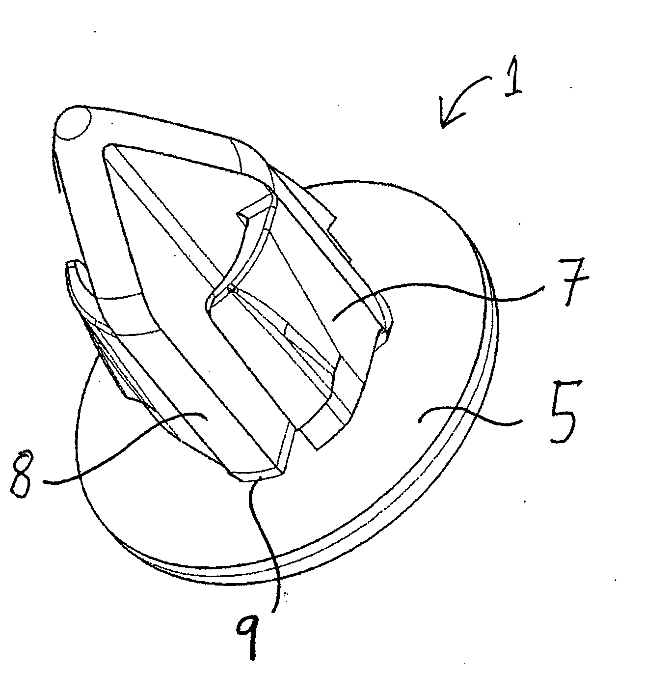
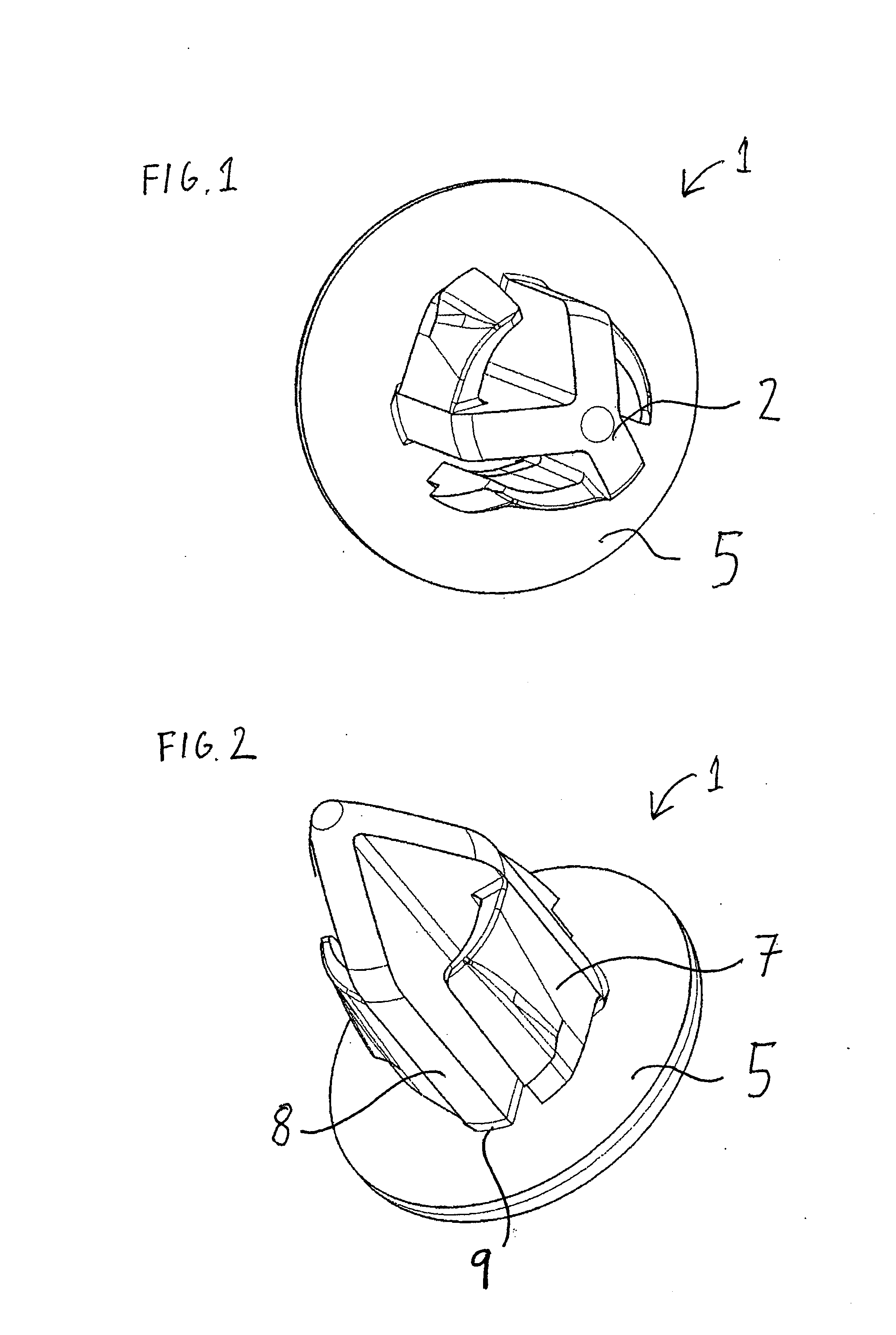
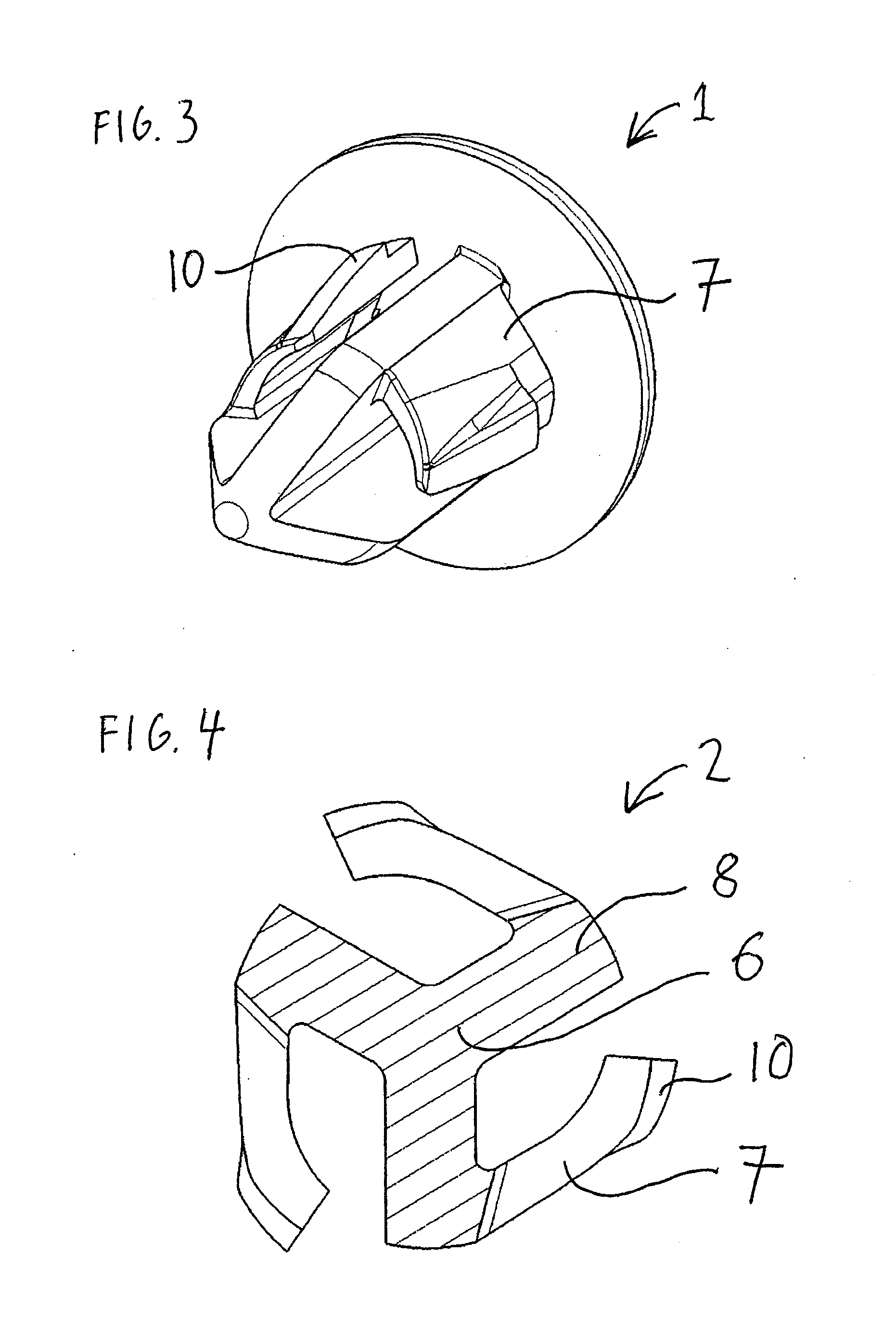
[0035]In FIG. 1-9 is described an embodiment of a fastening device 1 according to the invention. In FIG. 1 is described the fastening device 1 comprising a main portion 2 and a head 5. It is most clearly shown in FIG. 6 that the main portion 2 is provided with a base end portion 3 and a distal end portion 4. The main portion 2 comprises guiding elements 6 and resilient elements 7. In the disclosed embodiment comprises the guiding element three vanes 8. The construction of the main portion 2 is probably most clearly shown in FIG. 4 wherein a cross sectional view of the main portion 2 comprising the guiding element 6 is shown as the lined area comprising three vanes 8 and three resilient elements 7 attached to the vanes 8. The vanes 8 are spaced apart equidistantly from each other on the surface of the head 5 such that the peripheral parts of the bases 9 of the vanes 8 (most clearly shown in FIG. 2) are located at an equidistant distance from the centre of the main portion 2 (most cle...


PUM


Abstract

A fastening device comprising a main portion having a base end portion and a distal end portion wherein its base end is attached to a head intended to be in contact with a rim at the outer side of an aperture when the fastening device is located in the aperture. The main portion is provided with guiding elements in order to guide the fastening device when inserted into the aperture and resilient elements which during insertion will be pressed inwards in order to at a later stage, when the resilient elements have passed the rim of the aperture, resiliently move back and thus provide a locking of the fastening device by being in contact with the rim on the inside of the aperture. The guiding element is provided with at least three vanes which are attached at its bases to the head such that they are located at an essentially equidistant spacing from the centre point. The resilient elements are made up by segments which only are attached to the fastening device along one side of the segments to the vanes such that they are protruding from the vanes and extend in a direction towards an adjacent vane.

Description

TECHNICAL FIELD[0001]The invention relates to a fastening device (clip) which is used to attach different elements to each other, for example when mounting interior panels onto vehicles.BACKGROUND ART[0002]In order to join together devices, for example attachment of different kinds of panels in vehicles, screw joint reinforcements have earlier traditionally been used. However, screw joint reinforcements suffer from a number of disadvantages. The head of the screw will remain visible after attachment and should in some way be hidden or a less aesthetic appearance of the installation must be accepted. Furthermore, the mounting of a screw joint reinforcement is time consuming. In addition, such a mounting must be made manually why the use of a screw joint reinforcement in a manufacturing process is an obstacle concerning an automatization of the process.[0003]An increased interest in reducing mounting time and enabling automatization of the mounting has encouraged the search for altern...

Claims


Application Information

Patent Timeline
IPC IPC(8): F16B21/00
CPCF16B21/086F16B21/084Y10T24/42
Inventor OSTERGREN, KRISTIAN
Owner ITW SVERIGE
Why Eureka
Try Eureka