Bifurcated Electrical Contact

a technology of electrical contacts and bifurcated contacts, which is applied in the direction of coupling contacts, coupling devices, coupling devices, etc., can solve the problems of complex manufacturing, time-consuming and expensive processes, and interruption of circuits

Inactive Publication Date: 2010-12-23
PANCON ILLINOIS LLC
View PDF9 Cites 14 Cited by
  • Summary
  • Abstract
  • Description
  • Claims
  • Application Information

AI Technical Summary

Benefits of technology

[0006]A bifurcated electrical contact is provided with contact beams that respond differently to vibration so that the beams will not vibrate in unison, improving the opportunity for at least one of the beams to be in contact within a connector even under adverse conditions.

Problems solved by technology

This can result in situations in which both beams move away from the mating contact at substantially the same instant, thereby completely breaking electrical contact, causing circuit interruption.
Stronger springs or spring designs in the contact can overcome some vibration; however, this can result in a contact that is difficult to plug and unplug due to the stiff and unyielding nature of the more strongly biased contact beams, or a contact that is undesirably bulky.
In some situations, such as electrical connections in vehicle transmissions, complex connectors having pins or other components have been used, manufactured by more complex, time consuming and expensive processes such as welding or the like.
Known designs of connectors for use in such applications have been undesirably complex.

Method used


Image

  • Bifurcated Electrical Contact
  • Bifurcated Electrical Contact
  • Bifurcated Electrical Contact

Examples


Embodiment Construction

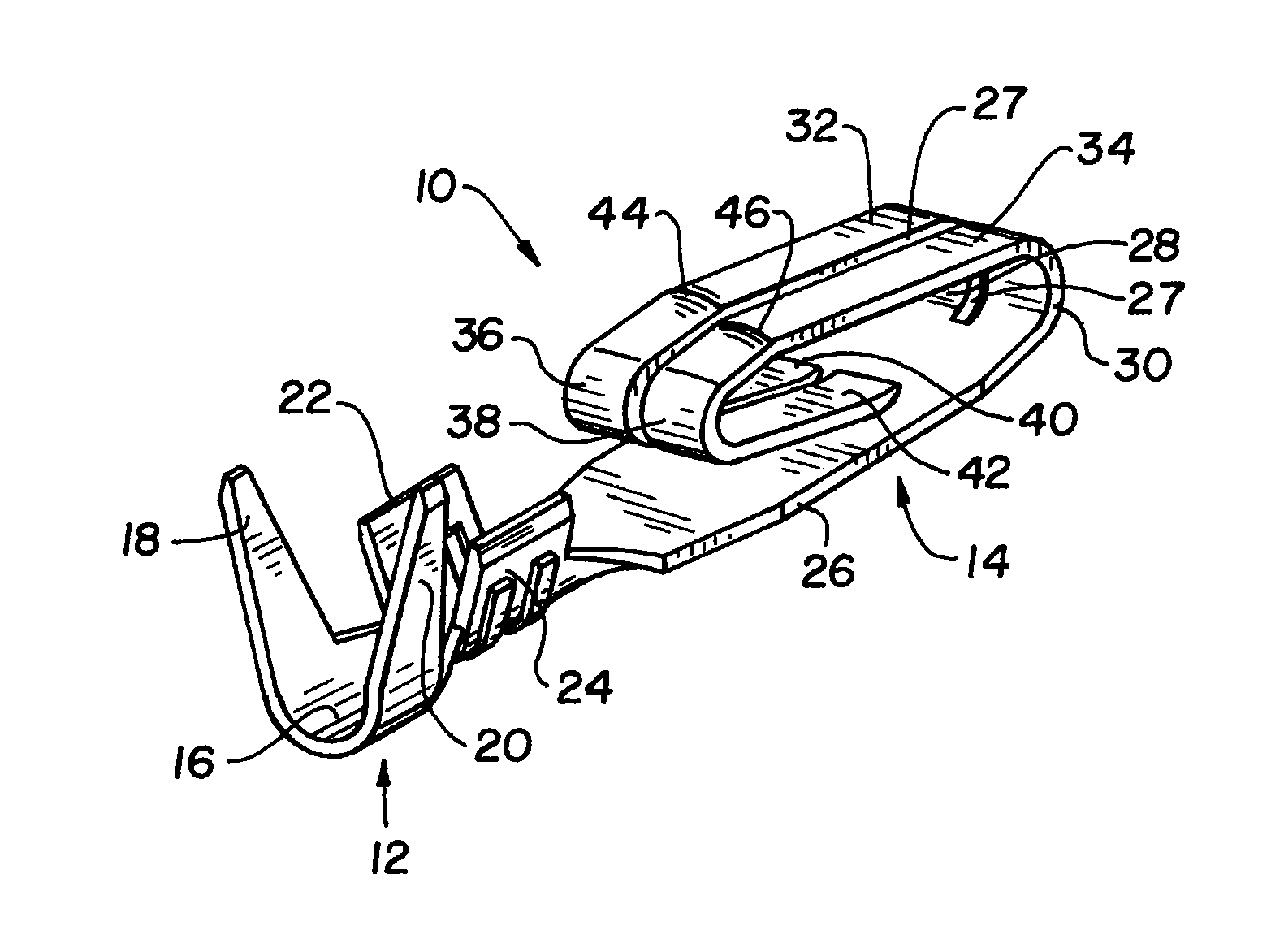
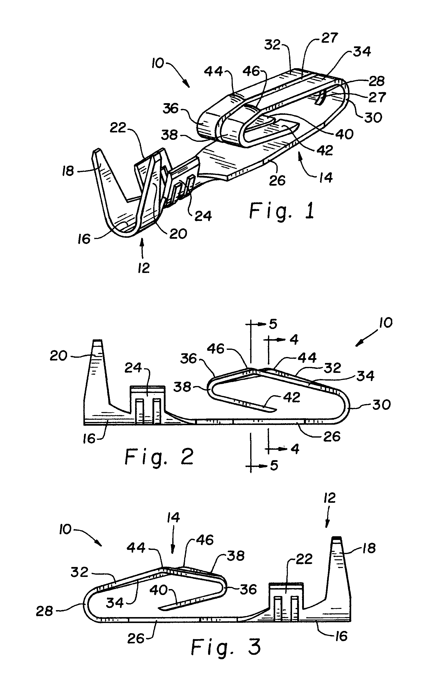
[0021]Referring now more particularly to the drawings and to FIG. 1 in particular, a bifurcated electrical contact 10 is shown. Contact 10 is a monolithic body of conductive material, such as conductive metal. Contact 10 includes a fastener portion 12 by which the contact is physically attached and electrically connected to a wire or cable. Contact 10 further includes an electrical contact portion 14 by which electrical connection is made to another system component by plug-in type connection of contact 10 to the other component.

[0022]Fastener portion 12 includes a trough-like base 16 for receiving a wire or cable. Opposed outer arms 18, 20 are provided for wrapping around and grasping the insulation or sheath of a wire or cable to which contact 10 is to be connected. Fastener portion 12 further includes somewhat smaller opposed inner arms 22, 24 for wrapping around and electrically connecting to the bared conductor of the wire or cable. Accordingly, contact 10 is physically connect...


PUM


Abstract

A bifurcated electrical contact includes first and second contact beams of different beam lengths and contact zones curved transverse to the beam lengths.

Description

CROSS-REFERENCE TO RELATED APPLICATIONS[0001]The present application claims the benefits of U.S. Provisional Application Ser. No. 61 / 218,702 filed Jun. 19, 2009.FIELD OF THE INVENTION[0002]The present invention relates generally to electrical contacts and connectors, and more specifically to contacts that are provided on wire ends for plugging connection to another electrical component.BACKGROUND OF THE INVENTION[0003]It is known to provide electrically conductive bodies, often referred to as “contacts” on the ends of wires or cables for devices that may require connection and disconnection for installation, service, repair or replacement. The contact is connected electrically to the wire or cable by crimping, soldering, electrically conductive bonding agents, or the like. It is known to provide the contact as a comparatively rigid metal body of electrically conductive material that can withstand a required frequency of plugging and unplugging into and from another system component....

Claims


Application Information

Patent Timeline
Patent Type & Authority Applications(United States)
IPC IPC(8): H01R4/48
CPCH01R4/185H01R4/188H01R13/2457H01R24/62H01R13/533H01R13/627H01R13/26
Inventor CLARK, STEPHEN H.RUSSELBURG, KEVIN L.JANOTA, NEIL E.
Owner PANCON ILLINOIS LLC
Why Eureka
Try Eureka