
Controlling an alarm in a medical instrument

a technology for controlling an alarm and a medical instrument, applied in the field of controlling an alarm in a medical instrument or a system, can solve the problems of alarms that cannot be sufficiently avoided, alarm delays, etc., and achieve the effect of reducing the delay of running alarms and shortening the delay

Active Publication Date: 2010-12-23
KONINKLIJKE PHILIPS ELECTRONICS NV
View PDF25 Cites 21 Cited by
  • Summary
  • Abstract
  • Description
  • Claims
  • Application Information

AI Technical Summary

Benefits of technology

[0015]Generally, it is possible that the function of at least one detected value of the physiological parameter allows for very short and very long alarm delays. However, according to a preferred embodiment of the invention, a maximum alarm delay and / or a minimum alarm delay are defined. Especially when the function is defined by a mathematical formula, this way it can be avoided to generate very long alarm delays in case the present value of the physiological parameter deviates from the normal value by only a small amount.
[0017]Generally, it is possible to keep the alarm delay fixed. However, according to a preferred embodiment of the invention, the value of the alarm delay is continuously updated according to a function of at least one detected value of the physiological parameter. This means that, according to this preferred embodiment of the invention, the limit violation counter starts running when the detected value of the physiological parameter exceeds or under-runs the predefined threshold for the first time, wherein the alarm delay changes according to a change of the detected value of the physiological parameter.
[0020]According to a further preferred embodiment of the invention, a subsequently running alarm delay is reduced by the present reduction value. This means that the limit violation counter does not start from zero if another exceeding or under-running of the threshold has occurred shortly before. This way, severe and deteriorating conditions of the patient can be indicated by an alarm reliably and with short delay.

Problems solved by technology

However, in order to avoid nuisance alarms it is known to use an alarm delay between the event of exceeding or under-running a preset limit and the actual generation of the alarm.
However, with this method and apparatus nuisance alarms cannot be sufficiently avoided because the integral continues to increase as long as the measured physiological value is above the threshold, even if the amount of how much the threshold is passed is decreasing, i.e. the patient's condition is improving.

Method used


Image

  • Controlling an alarm in a medical instrument
  • Controlling an alarm in a medical instrument
  • Controlling an alarm in a medical instrument

Examples


first embodiment

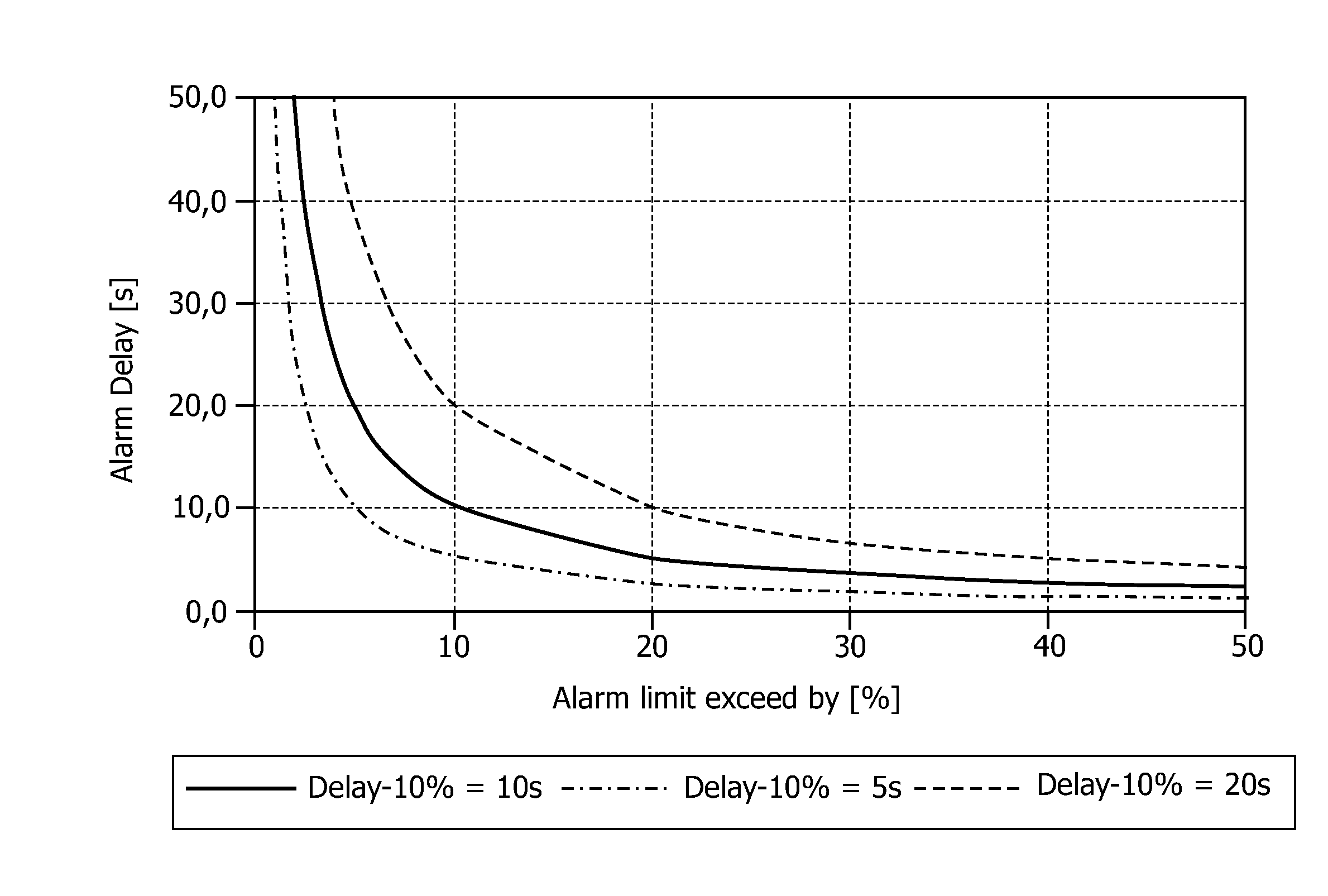
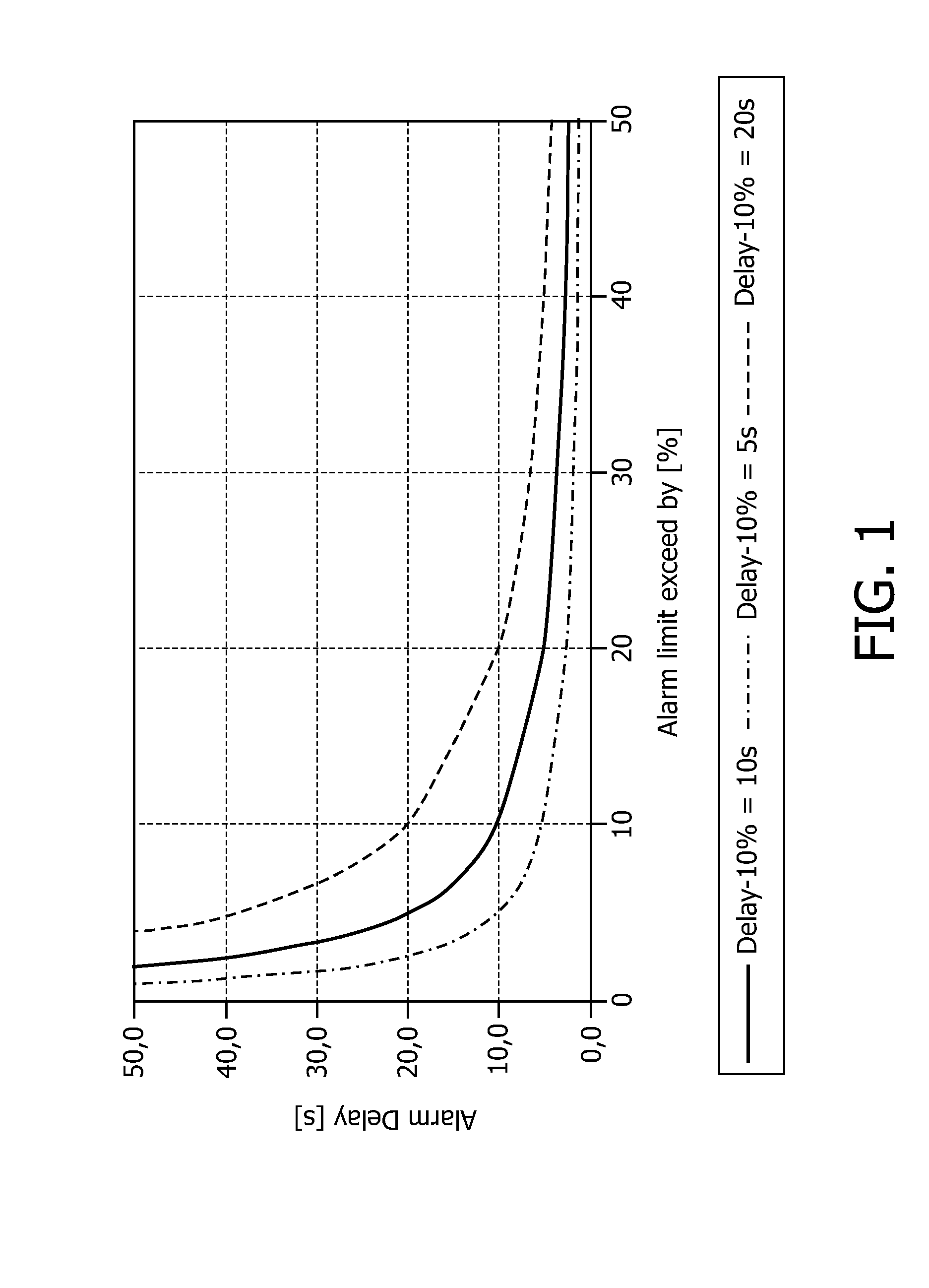
[0034]According to the invention the alarm delay is calculated by the following formula:

A(nT)=abs(L / (V(nT)−L))*Dx %*X % / 100%  (1),

[0035]wherein:

[0036]A(nT)=alarm delay at nT

[0037]T=update period

[0038]L=normal value or upper or lower limit of a[0039]normal range

[0040]V(nT)=value of the physiological parameter at nT

[0041]Dx %=selected alarm delay at X % exceeding of the alarm limit (L).

[0042]Graphs of the according curves of the alarm delay versus the percentage by which the normal value or limit is exceeded are shown in FIG. 1. As can be seen from FIG. 1, small percentages cause high alarm delays according to formula (1). Accordingly, in order to avoid too long delays, the alarm delay calculated according to formula (1) can be limited by a minimum value and / or a maximum value. A minimum alarm delay is beneficial to prevent nuisance alarms resulting from brief changes of the physiological value which might be caused by artifacts. Further, a maximum alarm delay ensures that an alarm is...

second embodiment

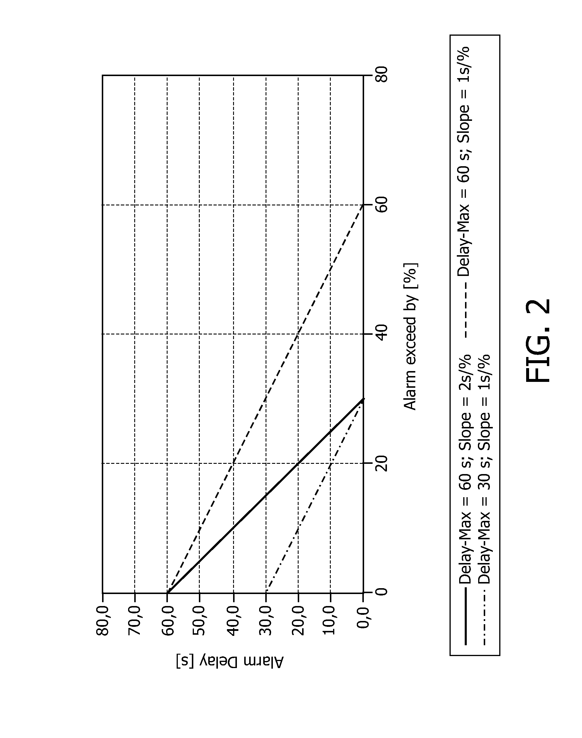
[0043]According to the invention, the following formula can be used to calculate the alarm delay:

A(nT)=Dmax−S*abs(V(nT)−L) / L  (2),

[0044]wherein:[0045]A(nT)=alarm delay at nT[0046]T=update period[0047]L=normal value or upper or lower limit of a normal range[0048]V(nT)=value of the physiological parameter at nT[0049]Dmax=maximum alarm delay[0050]S=slope with which the alarm delay decreases if the amount by which the physiological value exceeds the alarm limit increases.

[0051]This formula does not only consider the amount by which the physiological value exceeds the limit but also takes also into consideration the slope with which the alarm delay decreases if the amount by which the physiological value exceeds the alarm limit increases. The graph of according curves can be seen from FIG. 2. An offset may be added to formula (2) to get a minimum alarm delay.

[0052]From FIG. 3 an example for generating an alarm according to the first preferred embodiment of the invention can be seen. The ...

third embodiment

[0053]According to the invention, as shown below, a look-up table for the alarm delay is used instead of a formula:

relative amount by whichresulting alarmthe limit is exceededdelay60 s10 to 20%20 s20 to 30%12 s30 to 40% 9 s40 to 50% 7 s>50% 5 s

[0054]Further, instead of making the alarm delay dependent on the absolute or relative amount by which the limit is exceeded or under-run, the alarm delay can be made dependent on the absolute value of the physiological parameter, the relative or absolute deviation of the physiological parameter from a normal value or the relative or absolute deviation from any predefined values.

[0055]For measuring the time since the physiological parameter has exceeded the upper limit or has under-run the lower limit, the limit violation timer is started as soon as the physiological value has crossed the according limit, respectively. At each time interval T the current alarm delay is calculated based on the current value of the physiological parameter and th...


PUM


Abstract

The invention concerns a method for controlling an alarm in a medical instrument or system, the medical instrument or system detecting at least one physiological parameter of the patient. The present value of the physiological parameter is consecutively detected and an alarm delay is determined as a function of at least one detected value of the physiological parameter wherein the function yields a shorter alarm delay for increasing values of the deviation from a normal value and a longer alarm delay for decreasing values of the deviation from the normal value. Further, the duration the value of the physiological parameter exceeds or under-runs at least one predefined threshold for the physiological parameter defining an upper or lower limit for a normal range of the physiological parameter, respectively, is measured and the alarm is generated when the duration the determined value of the physiological parameter exceeds or under-runs the predefined threshold exceeds the alarm delay. This method allows for the avoidance of nuisance alarms while still indicating severe conditions of the monitored patient reliably.

Description

FIELD OF THE INVENTION[0001]The invention relates to the field of controlling an alarm in a medical instrument or system, the medical instrument or system detecting at least one physiological parameter of the patient.BACKGROUND OF THE INVENTION[0002]Typical patient monitoring systems and some other medical instruments and systems measure different physiological values, and, thus, can provide measurements of ECG, respiration, SpO2, blood pressure etc. If a detected physiological parameter exceeds or under-runs a preset limit an alarm is generated.[0003]However, in order to avoid nuisance alarms it is known to use an alarm delay between the event of exceeding or under-running a preset limit and the actual generation of the alarm. Such an alarm delay is often a compromise between warning the clinical staff fast enough about a change in the patient's condition on the one hand and generation of too many unjustified and, thus, nuisance alarms which detract the clinical staff from other wo...

Claims


Application Information

Patent Timeline
Patent Type & Authority Applications(United States)
IPC IPC(8): A61B5/00G06F19/00
CPCA61B5/021A61B5/02455A61B5/746G06F19/3406A61M2230/00A61N1/08A61N1/37258A61M2205/18G16H40/63
Inventor WOEHRLE, DIETER
Owner KONINKLIJKE PHILIPS ELECTRONICS NV
Learn More