Transcranial electrical stimulation device

a transcranial electrical stimulation and electrode technology, applied in the direction of head electrodes, internal electrodes, therapy, etc., can solve the problems of inability to accurately position the electrodes to the predetermined position of the patient's head, time required for mounting electrodes, and inability to accurately stimulate the motor area of the cerebral cortex. , to achieve the effect of stimulating the motor area of the cerebral cortex, stable potential, and sufficient stimulation

Inactive Publication Date: 2010-12-23
HIROSHIMA UNIVERSITY
View PDF4 Cites 5 Cited by
  • Summary
  • Abstract
  • Description
  • Claims
  • Application Information

AI Technical Summary

Benefits of technology

[0031]In this way, by only wearing the wearing equipment on a patient's head, the electrodes can be accurately positioned at predetermined positions of a patient's head so that it can be effectively stimulating the motor area of a cerebral cortex. Since the distance between the electrode and the motor area of a patient's cerebral cortex is approximately constant, the motor area can be stimulated with a stable potential.
[0032]Since it is possible to generate sufficient stimulation by setting the electrode subcutaneously due to using a screw electrode, it is unnecessary to bore a patient's skull outer layer with a drill, and mounting of the electrode can be performed in a short time. Moreover, it is easily mountable to the head and is also minimally invasive.
[0033]Particularly, t

Problems solved by technology

However, on the contrary, there also are problems such as the following.
Although there is no serious report for complications up till now in the conventional method, time was required to mount the electrode since the bone had to be bored.
If an emission of an evoked potential is difficult, there are cases where a change

Method used


Image

  • Transcranial electrical stimulation device
  • Transcranial electrical stimulation device
  • Transcranial electrical stimulation device

Examples


Embodiment Construction

[0042]The embodiments of the present invention are described with reference to the drawings.

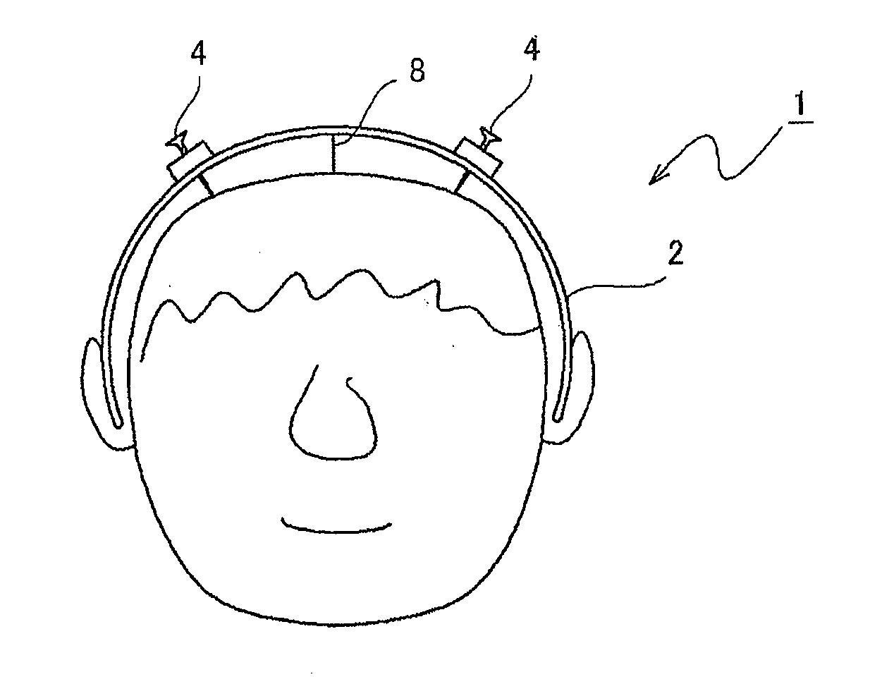
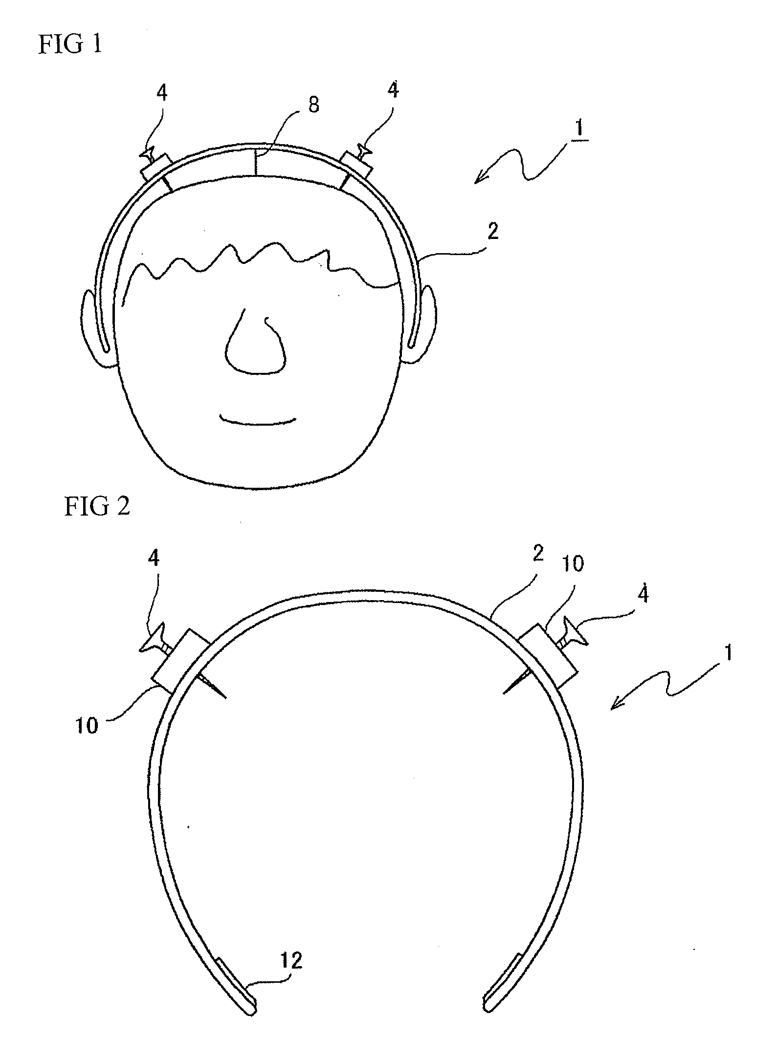
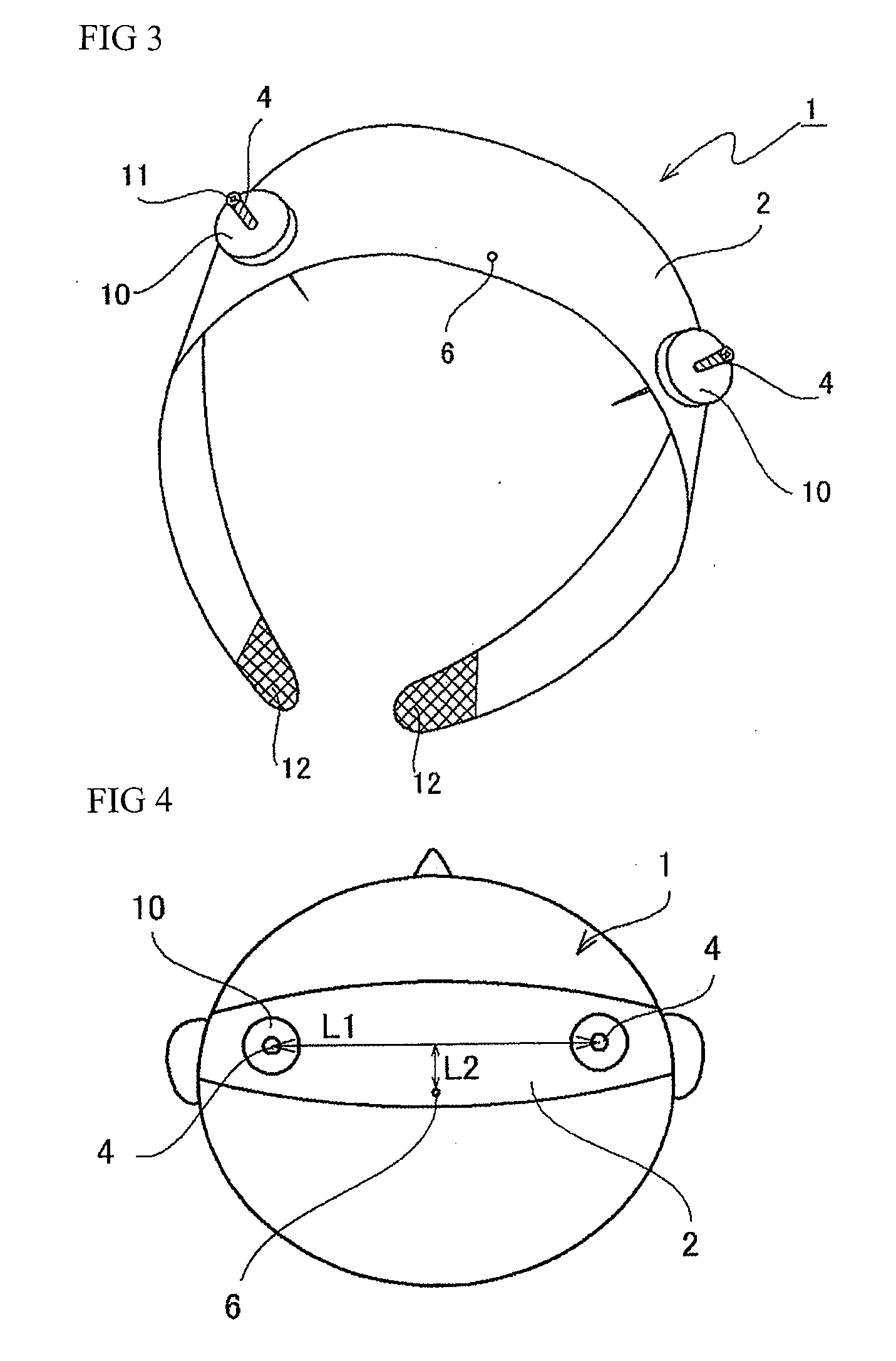
[0043]As shown in FIGS. 1-4, a transcranial electrical stimulation device 1 comprises a wearing equipment 2 which is detachably worn on a patient's head, and at least a pair of electrodes 4 attached to the wearing equipment 2.

[0044]The wearing equipment 2 comprises an arch-shaped plate capable of an elastic deformation. The wearing equipment 2 can be formed of an electrical insulating plastic with elasticity, and also can be constituted by a metal plate and the like. When forming the wearing equipment 2 with a metal plate, it is preferable to cover the surface of the metal plate with an electrical insulating resin.

[0045]Fastening parts 12 for securing the wearing equipment 2 onto a patient's head can be provided to both ends of the wearing equipment 2. The fastening parts 12 can be constituted by a sheet-like fastener. In that case, a chin strap having a sheet-like fastener provided to both e...


PUM


Abstract

A transcranial electrical stimulation device 1 having a wearing equipment 2 detachably worn onto a patient's head and at least a pair of electrodes 4 attached to the wearing equipment 2, the device for electrically stimulating a motor area of a patient's cerebral cortex by outputting current from the electrode 4 connected to a current generator. An engagement part 6 capable of engaging the wearing equipment 2 to a scalp with a thread-like body 8 is provided to the wearing equipment 2, and the electrode 4 is attached to the wearing equipment 2 protrudably to the head side of the electrode 4, and tip of the electrode 4 is capable of subcutaneously piercing through the head. It is unnecessary to bore a patient's skull outer layer with a drill, and a mounting of the electrode can be performed in a short time. The electrodes can be accurately positioned at predetermined positions of a patient's head, and the motor area of a cerebral cortex can be effectively stimulated.

Description

TECHNICAL FIELD[0001]The present invention relates to a transcranial electrical stimulation device capable of accurately positioning electrodes at predetermined positions of a patient's head and capable of effectively stimulating the motor area of a cerebral cortex.BACKGROUND ART[0002]A transcranial electrical stimulation method is a method for electrically stimulating the motor area of a cerebral cortex. The method was reported by Levy et al. in 1984 (Levy, 1984), and at the same time, the method was immediately spread all over the world.[0003]The transcranial electrical stimulation method is widely used mainly for the purpose of spinal cord lesion segment diagnosis in a spinal cord disorder or for performing spinal cord function monitoring during surgery of a spinal cord tumor and the like (Mckay, 1997). Since spinal cord lesion segment diagnosis can functionally diagnose the lesion segment of the spinal cord disorder, the certainty of the treatment was dynamically improved.[0004]...

Claims


Application Information

Patent Timeline
IPC IPC(8): A61N1/05
CPCA61N1/0531A61N1/36017A61N1/32A61N1/0472A61N1/321A61N1/36025
Inventor TANAKA, NOBUHIRONAKANISHI, KAZUYOSHI
Owner HIROSHIMA UNIVERSITY
Why Eureka
Try Eureka