Eureka AIR delivers breakthrough ideas for toughest innovation challenges, trusted by R&D personnel around the world.

Electrically isolating electrical components in a medical electrical lead with an active fixation electrode

a technology of electrical components and active fixation electrodes, which is applied in the direction of spinal electrodes, inductances, therapy, etc., can solve the problem of preventing the flow of mri-induced rf current into body tissue,

Active Publication Date: 2010-12-23
WILSON GREATBATCH LTD
View PDF6 Cites 33 Cited by
  • Summary
  • Abstract
  • Description
  • Claims
  • Application Information

AI Technical Summary

Benefits of technology

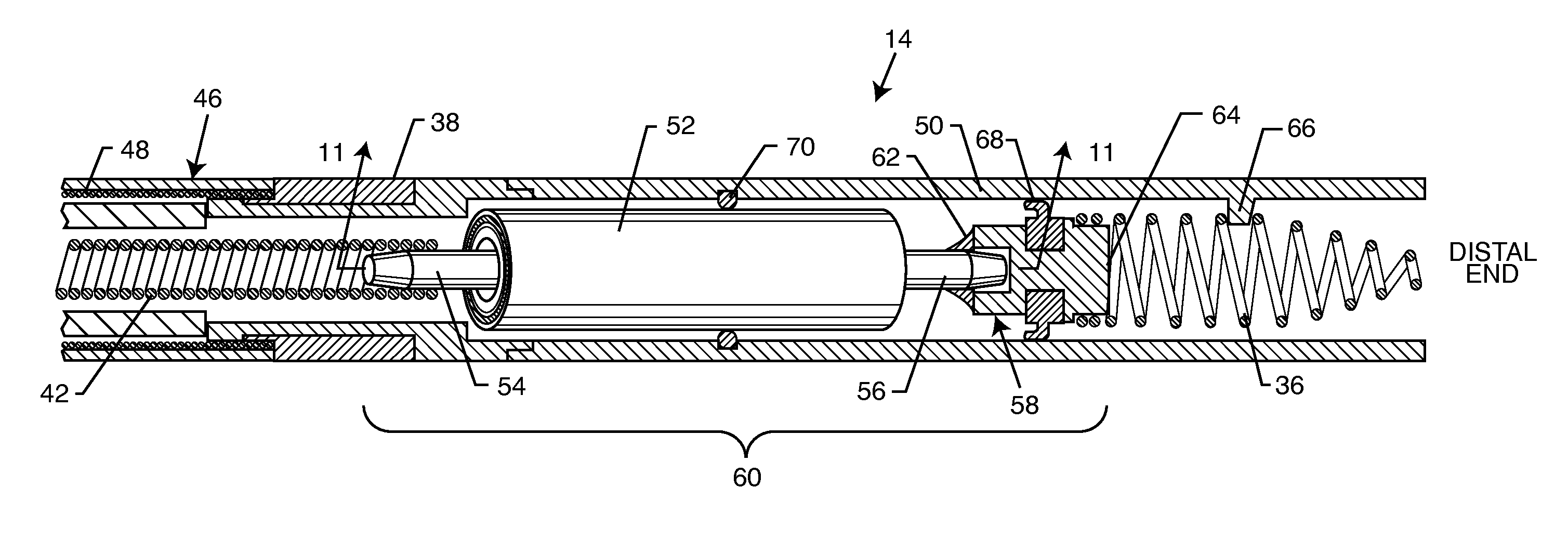
[0007]The seal may be disposed at a distal end of the casing, at a proximal end of the casing, or even along a middle of the casing. Furthermore, the seal may be fixed relative to the casing or the collar. The electrical component may comprise a bandstop filter or other electronic circuits such as electronic switches. The seal prevents ingress of bodily fluids inside the lead body and electrically isolates the electronic component and the pins of the casing. Isolating the pins extending in non-conductive relationship with the casing from each other is very important. For example, a bandstop filter may present an impedance of 2000 ohms at resonance. This desirably impedes the flow of MRI induced RF current into body tissue through the electrode. However, if the pins are not isolated from each other, a parallel path through body fluids (ionic fluid) could result in a parallel path of approximately 80 ohms. This conduction through surrounding fluid would degrade the MRI RF signal attenuation. Accordingly, it's very important to be able to isolate the opposite ends of the pins of the electronic component.

Problems solved by technology

This desirably impedes the flow of MRI induced RF current into body tissue through the electrode.

Method used


Image

  • Electrically isolating electrical components in a medical electrical lead with an active fixation electrode
  • Electrically isolating electrical components in a medical electrical lead with an active fixation electrode
  • Electrically isolating electrical components in a medical electrical lead with an active fixation electrode

Examples


Embodiment Construction

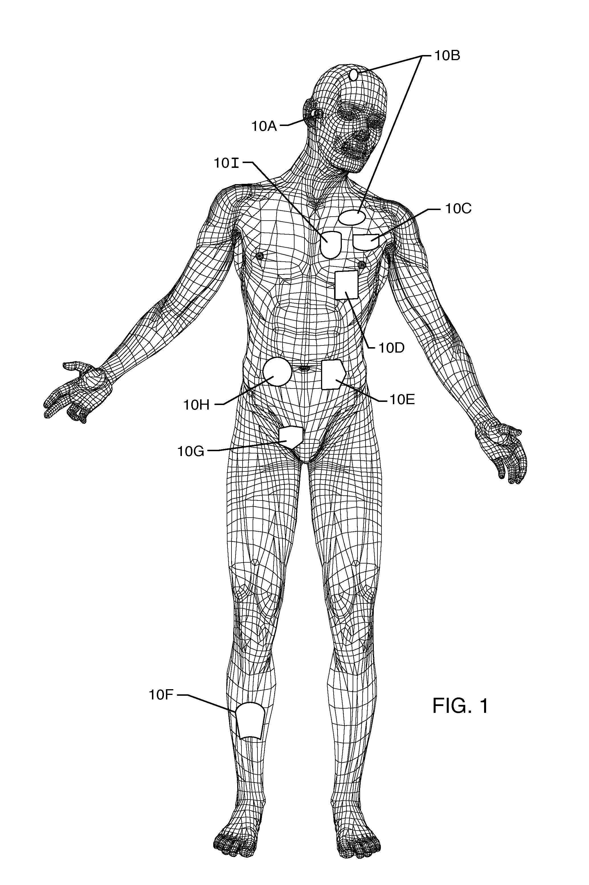
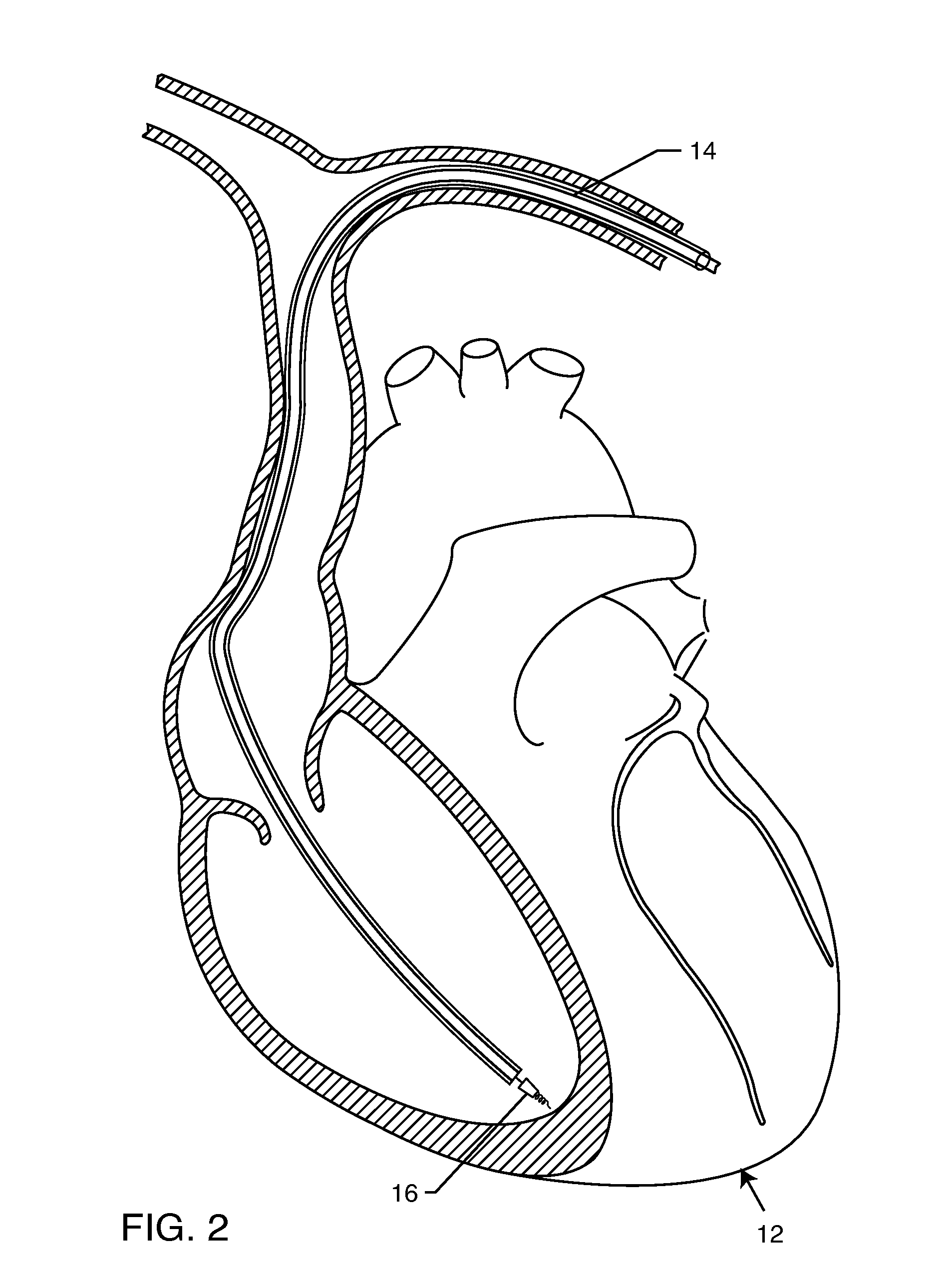
[0033]FIG. 1 is a wire formed diagram of a generic human body showing a number of implanted medical devices. 10A represents a family of hearing devices which can include the group of cochlear implants, piezoelectric sound bridge transducers and the like. 10B represents a variety of neurostimulators and brain stimulators. Neurostimulators are used to stimulate the Vagus nerve, for example, to treat epilepsy, obesity and depression. Brain stimulators are pacemaker-like devices and include electrodes implanted deep into the brain for sensing the onset of the seizure and also providing electrical stimulation to brain tissue to prevent the seizure from actually occurring. 10C shows a cardiac pacemaker which is well-known in the art. 10D includes the family of left ventricular assist devices (LVAD's), and artificial hearts, including the recently introduced artificial heart known as the Abiocor. 10E includes an entire family of drug pumps which can be used for dispensing of insulin, chemo...


PUM


Abstract

A lead body adapted for in-vivo implantation in a living subject includes a proximal end configured for electrical and mechanical connection to a therapy or a monitoring device, and a distal end. A collar is disposed at the distal end of the lead body, and a casing is disposed within the collar and is translatable along a central longitudinal axis of the collar. At least one electrical conductor extends substantially the length of the lead body, and an electronic component is disposed within the casing and conductively coupled to the electrical conductor. An electrode is mechanically connected to the casing and conductively coupled to the electronic component. A seal is disposed between the casing assembly and the collar to prevent passage of ionic fluid into the lead body through its distal end.

Description

FIELD OF THE INVENTION[0001]The present invention generally relates to implantable medical electrical leads. More particularly, the present invention relates to a lead body adapted for in-vivo implantation in a living subject.BACKGROUND OF THE INVENTION[0002]A wide assortment of implantable medical devices are presently known and in commercial use. Such devices include cardiac pacemakers, cardiac defibrillators, cardioverters, neurostimulators, and other devices for delivering and / or receiving electrical signals to / from a portion of the body. Sensing and / or stimulating leads extend from the associated implantable medical device to a distal tip electrode or electrodes in contact with body tissue. These electrodes should be securely fixed to the tissue to facilitate electrical stimulation or sensing by the implantable medical device.[0003]In order to work reliably, leads need to be stably located adjacent to the tissue to be stimulated or monitored. One common mechanism for accomplish...

Claims


Application Information

Patent Timeline
IPC IPC(8): A61N1/05
CPCA61N1/05A61N1/0551A61N1/0573A61N1/3718A61N2001/086H03H2007/013H01F27/40H01F2017/065H03H1/0007H03H7/0115H03H2001/0042H01F27/027A61N1/086
Inventor BAUER, RYAN THOMASBRAINARD, SCOTTKANE, LAWRENCE M.DABNEY, WARREN S.JOHNSON, ROBERT SHAWNSTEVENSON, ROBERT A.MOSCHIANO, HOLLY NOELLE
Owner WILSON GREATBATCH LTD
Why Eureka
Eureka Blog
Learn More