Component based software system

a software system and component technology, applied in the direction of source code generation, instruments, requirement analysis, etc., can solve the problems of inability to express the functionality inside the component, inability to achieve successful development and deployment of software technologies, and the choice of software technology used to create software further complicates system developmen

Active Publication Date: 2010-12-23
RAMCO SYSTEMS
View PDF11 Cites 64 Cited by
  • Summary
  • Abstract
  • Description
  • Claims
  • Application Information

AI Technical Summary

Problems solved by technology

The inability to achieve successful development and deployment in software technologies is a problem in the struggle towards creating practical software components.
This is compounded by the fact that on a micro-level, the functionality inside the component is not expressible in a standard way for users to understand before they assemble an application using components.
The choice of technologies used to create software further complicates system development because of the lack of standard architectural or structural elements in describing software.
Moreover, the functionality provided by software components cannot be abstracted to a reasonably finite set at any point in time.
However, such data sheet based specifications are not available for software components.
Consequently, problems faced by the industry in making software components include a lack of a standard definition, a lack of an independent production approach, a lack of transparency in functionality and interface properties, and a lack of support needed for making available respective data sheets, assembly instructions, and engineering instructions.
However, none of the prior attempts were very successful, as they got caught up in the modeled logic, the programming language, or the tediousness of the approach.
First, attempts to generate code for a logic model required extensive detail work at the specification level.
Second, even when specifications were used, there has been no standardization of the specification and/or the formal data structures that store and retrieve information.
Third, a much needed Change Management process has not been thought out and implemented, causing specifications and models to be out of sync and rendering forward enginee

Method used


Image

  • Component based software system
  • Component based software system
  • Component based software system

Examples


Embodiment Construction

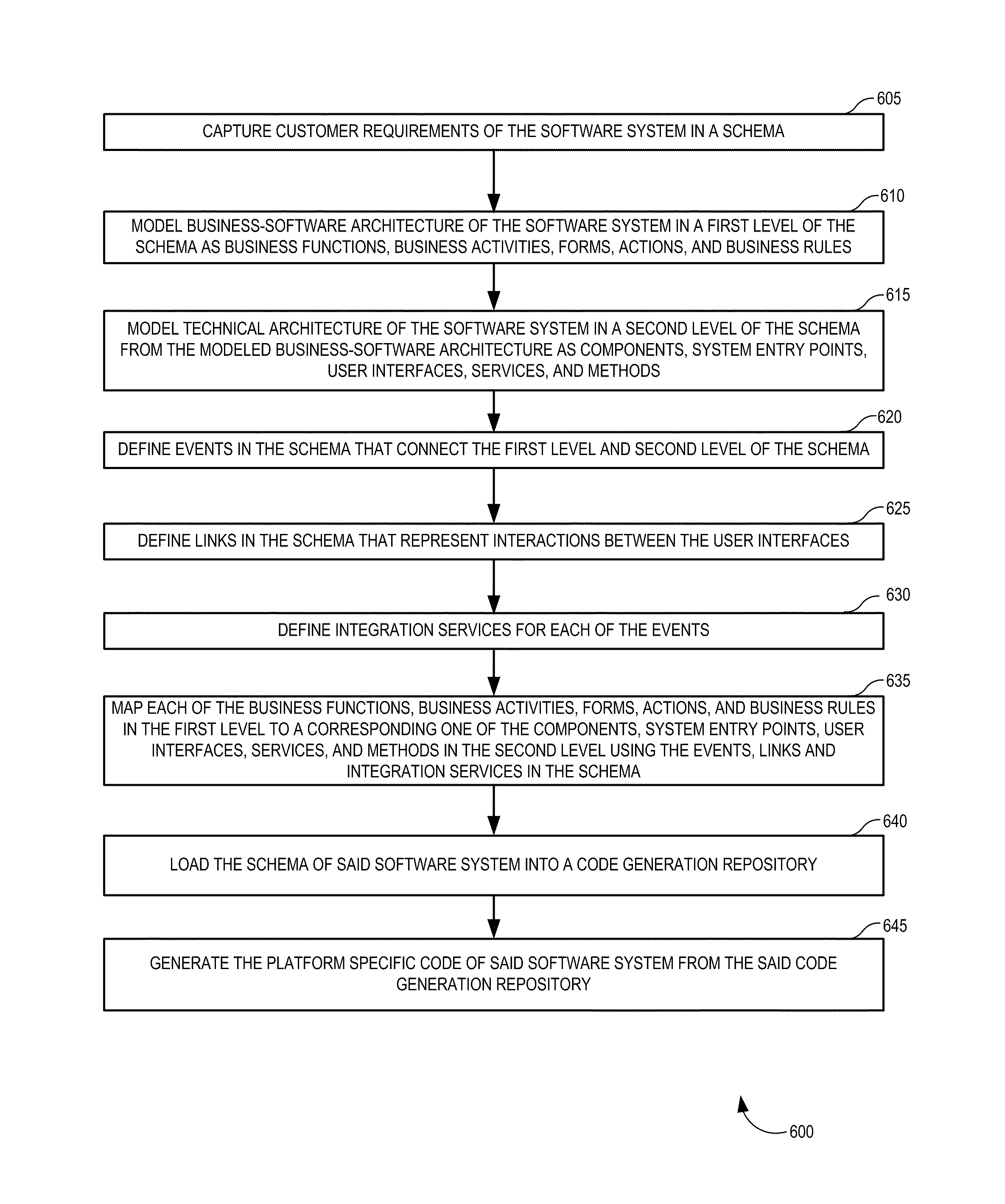
[0022]A method and system for component based software system to generate platform specific code for a user interface in a software system is disclosed. In the following description, for purposes of explanation, numerous specific details are set forth in order to provide a thorough understanding of the present invention. It will be evident, however, to one skilled in the art that the present invention may be practiced without these specific details.

[0023]In one embodiment of the invention, a component is defined as a self-contained software application that encapsulates and implements a single function. The terms ‘task’, ‘business task’ and ‘action’ are used interchangeably throughout the document.

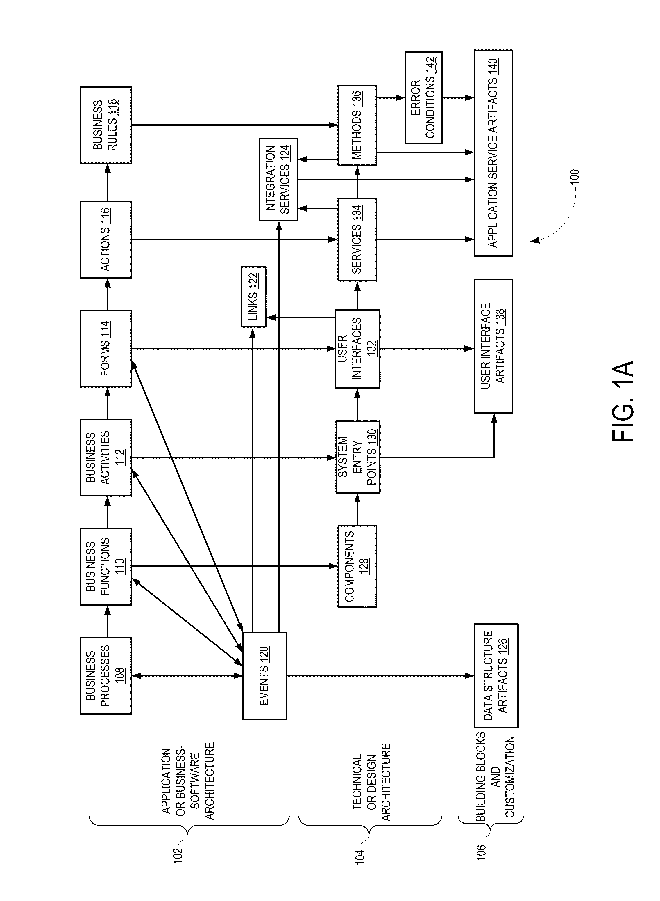
[0024]FIG. 1A is a schema 100 for gathering requirements and creating and managing enterprise software from the gathered requirements in accordance with one example embodiment of the present invention. The schema or software structure specification 100 includes multiple levels of abstracti...


PUM


Abstract

A computer implemented model-driven method to generate platform specific code for a user interface is disclosed. In one embodiment, the method includes, capturing customer requirements of the software component in a schema, modeling business-software architecture of the software component in a first level of the schema, modeling technical architecture of the software system from the modeled business-software architecture in a second level of the schema, defining events in the schema that connect the first level and the second level of the schema, defining links in the schema that represent interactions between the user interfaces, defining integration services in the schema for each of the events, mapping each element in the first level to a corresponding one of the elements in the second level using the events, links, and integration services in the schema, loading the schema of the software component into a code generation repository.

Description

RELATED APPLICATIONS[0001]Benefit is claimed under 35 U.S.C. 120 to U.S. Non Provisional application Ser. No. 11 / 029,989, entitled “COMPONENT BASED SOFTWARE SYSTEM” by inventor Sundararajan Parthasarathy et al., filed Jan. 5, 2005, which is herein incorporated in its entirety by reference for all purposes.FIELD OF THE INVENTION[0002]The present invention relates to component based software systems, and in particular, the development, testing, and deployment of such systems.BACKGROUND OF THE INVENTION[0003]Component-based software development is the current trend in software technologies. A software component may be thought of as a self-contained unit that encapsulates and implements the behavior of a single function.[0004]A complex software system for an organization that spans multiple business functions is normally made up of multiple components. And since the various functions in a business interact with each other, components also need to interact with each other. Development of...

Claims


Application Information

Patent Timeline
IPC IPC(8): G06F9/44G06F3/00
CPCG06F8/10G06F8/35
Inventor SUNDARARAJAN, PARTHASARATHYJAYARAMAN, SHYAMALASATHIAVAGEESWARAN, SURESHRAJARAMAN, MADUSUDANANRAMASWAMY, SRINIVASANMEENAKSHISUNDARAM, KRISHNAMOORTHYDEVALLA, RAGHURAMPONNAIAH, SHANMUGAVEL R.KRISHNAN, NATARAJAN
Owner RAMCO SYSTEMS
Why Eureka
Try Eureka