Glass substrate processing device using laser beam

a technology of laser beam and glass substrate, which is applied in glass tempering apparatus, glass making apparatus, manufacturing tools, etc., can solve the problems of long processing time, evaporation of glass substrate, burnt support portions of work tables, etc., and achieve the effect of low cos

Active Publication Date: 2010-12-30
MITSUBOSHI DIAMOND IND CO LTD
View PDF4 Cites 65 Cited by
  • Summary
  • Abstract
  • Description
  • Claims
  • Application Information

AI Technical Summary

Benefits of technology

[0036]Overall, the processing device according to the aspects can process a glass substrate with a laser beam in a shorter period of time than the well-known proc...

Problems solved by technology

This results in evaporation of the glass substrate.
However, a long processing time is required for the well-known method of processing a glass substrate ...

Method used


Image

  • Glass substrate processing device using laser beam
  • Glass substrate processing device using laser beam
  • Glass substrate processing device using laser beam

Examples


first exemplary embodiment

Modifications of First Exemplary Embodiment

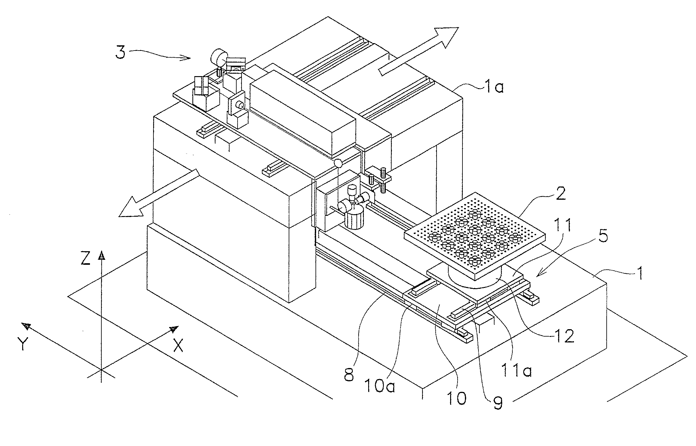
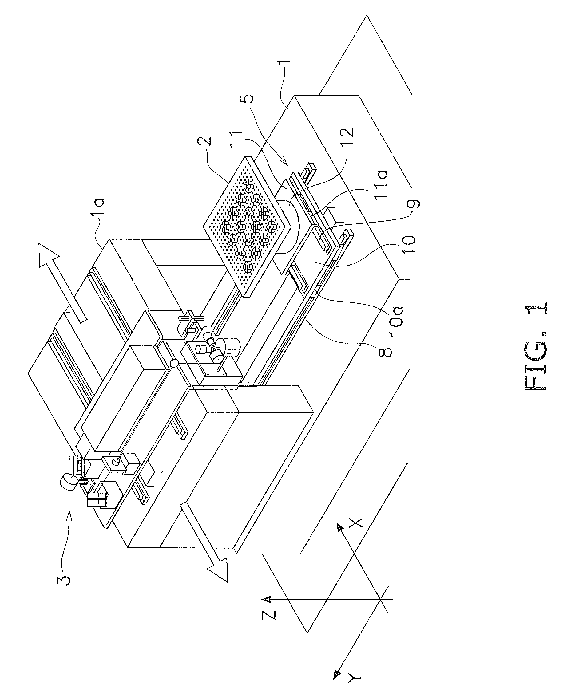
[0085](a) In the aforementioned exemplary embodiment, the z-coordinate directional moving mechanism 22 is used as a mechanism for moving the beam focus spots in the z-coordinate direction. Further, the z-coordinate directional moving mechanism 22 is configured to move the hollow motor 17, the x-directional galvano mirror 18, the y-directional galvano mirror 19, and the fθ lens 20 in the z-coordinate direction. However, the work table 2 may be configured to be moved in the z-coordinate direction without moving the hollow motor 17, the x-directional galvano mirror 18, the y-directional galvano mirror 19, and the fθ lens 20.

[0086](b) In the aforementioned exemplary embodiment, the fθ lens is used as a collective lens. However, the collective lens is not limited to the fθ lens as long as it can focus a laser beam.

Alternate Embodiments

[0087]Alternate embodiments will now be explained. In view of the similarity between the first and alternate emb...

second exemplary embodiment

Modification of Second Exemplary Embodiment

[0108]In the second exemplary embodiment, the z-coordinate moving device 22 is used as a mechanism of moving a beam focus spot in the z-coordinate direction. Specifically, the z-coordinate moving device 22 is configured to move the second hollow motor 118 including the collective lens 135. However, the work table 2 may be configured to be moved in the z-coordinate direction without moving the second hollow motor 118 including the collective lens 135.

Other Exemplary Embodiments

[0109]The present invention is not limited to the aforementioned exemplary embodiments. Various changes or modifications can be made for the aforementioned exemplary embodiments without departing from the scope of the present invention.

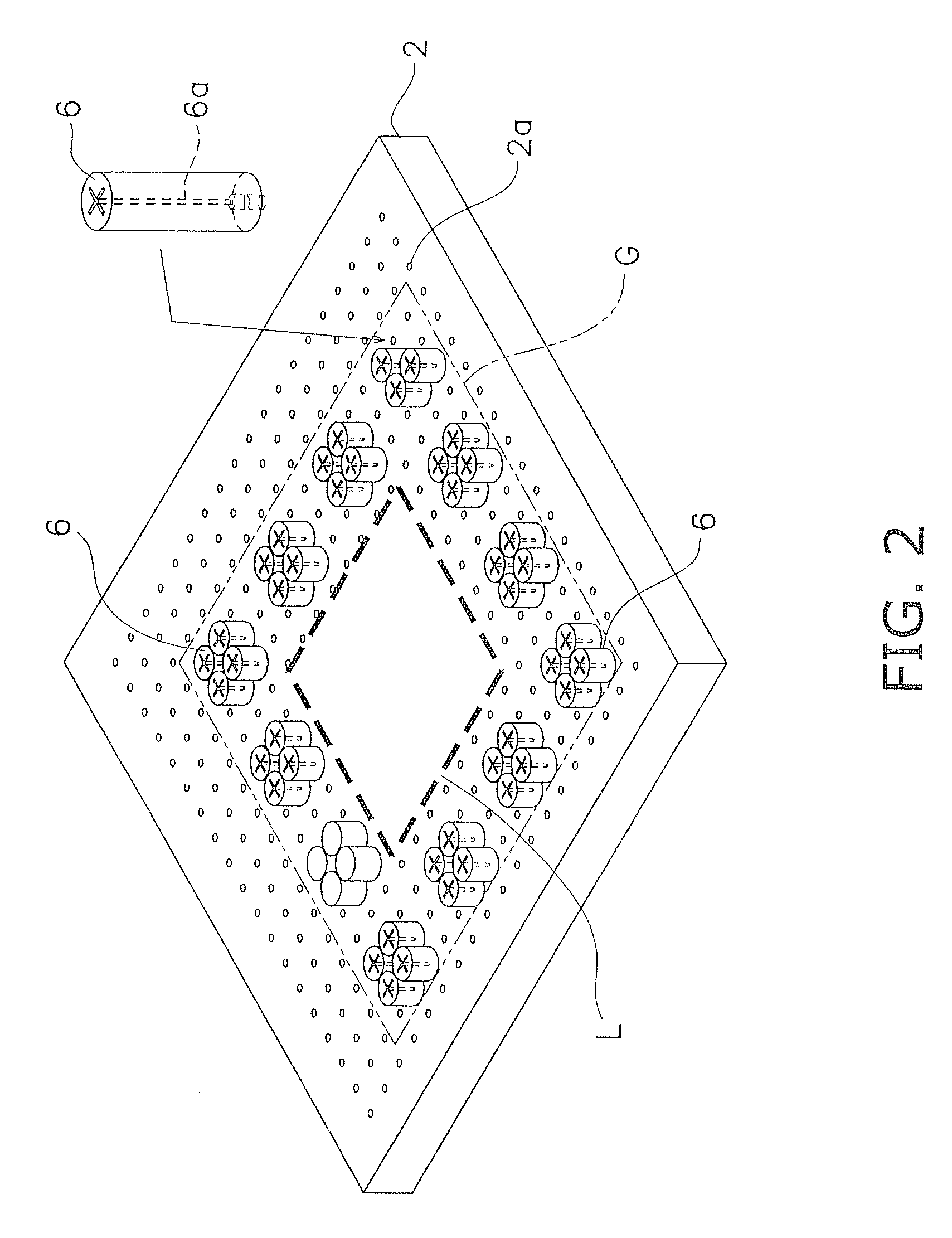
[0110](a) In the aforementioned exemplary embodiments, components including the diffractive optical element are configured to form four beam focus spots on the circumference of an imaginary circle at an interval of an equal angle, as ill...


PUM

PropertyMeasurementUnit
Angleaaaaaaaaaa
Radiusaaaaaaaaaa
Circumferenceaaaaaaaaaa

Abstract

A processing device is configured to irradiate a laser beam onto a glass substrate for processing. The processing device has a work table, a laser beam output section, a multi-spot focus section, a rotation drive mechanism, an optical system, and a laser beam scan section. The multi-spot focus section receives a laser beam, and splits and focuses the laser beam inputted therein into a plurality of beam focus spots. The rotation drive mechanism rotates the plurality of beam focus spots about a single center axis that is arranged in a center of the plurality of beam focus spots. The optical system guides the laser beam to the multi-spot focus section. The laser beam scan section moves all the plurality of beam focus spots rotating about the single center axis in a desired direction within a predetermined range of a plane arranged along a surface of the glass substrate.

Description

CROSS-REFERENCE TO RELATED APPLICATIONS[0001]This application claims priority to Japanese Patent Application Nos. 2009-154578 filed on Jun. 30, 2009 and 2009-154579 filed on Jun. 30, 2009, the entirety of which is hereby incorporated by reference.BACKGROUND[0002]1. Field of the Invention[0003]The present invention relates to a glass substrate processing device, more specifically, to a glass substrate processing device configured to process a glass substrate by laser beam irradiation.[0004]2. Background Information[0005]Japan Laid-open Patent Application Publication No. JP-A-2007-118054 describes a well-known glass substrate processing device using a laser beam. The processing device is configured to irradiate a green laser beam having a wavelength of roughly 532 nm onto a work such as a glass substrate. In general, a green laser beam penetrates the glass substrate. However, the laser beam is absorbed by the glass substrate under a condition that the laser beam is concentrated and in...

Claims


Application Information

Patent Timeline
IPC IPC(8): C03B23/00
CPCB23K26/0676B23K26/0807B23K26/386C03B33/03C03B33/0222C03B33/023B23K26/4075B23K26/082B23K26/40B23K26/389B23K2103/50
Inventor KUMATANI, ISSEISHIMIZU, SEIJI
Owner MITSUBOSHI DIAMOND IND CO LTD
Why Eureka
Try Eureka