
Method and apparatus for gas removal

a gas removal and gas technology, applied in the direction of electric supply techniques, dispersed particle separation, separation processes, etc., can solve the problems of inability to economically viable cosub>2 /sub>gas separation, cryogenics are considered prohibitively expensive, and amine scrubbing is currently used only on a small commercial scal

Inactive Publication Date: 2010-12-30
SRI INTERNATIONAL
View PDF9 Cites 35 Cited by
  • Summary
  • Abstract
  • Description
  • Claims
  • Application Information

AI Technical Summary

Benefits of technology

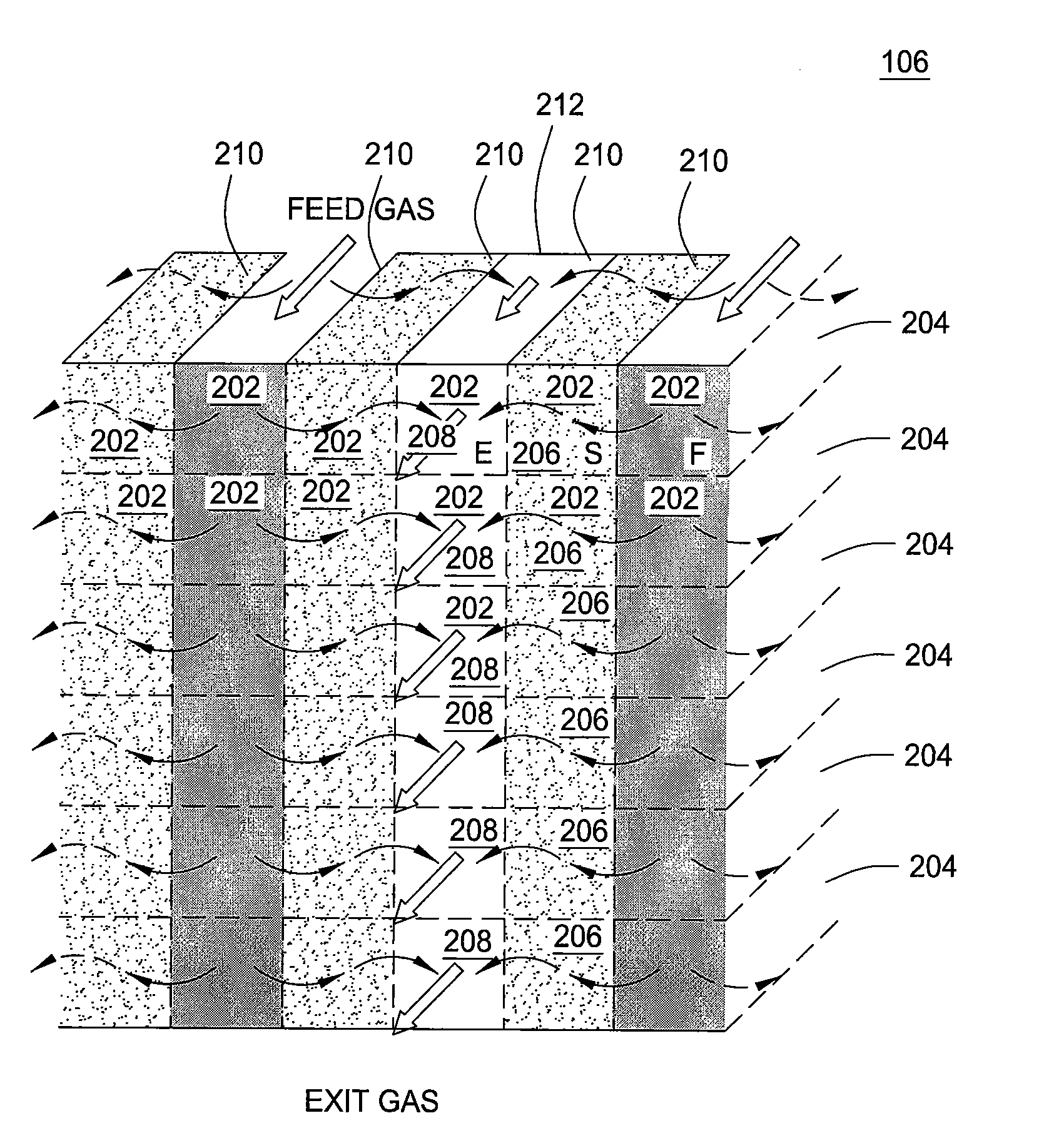
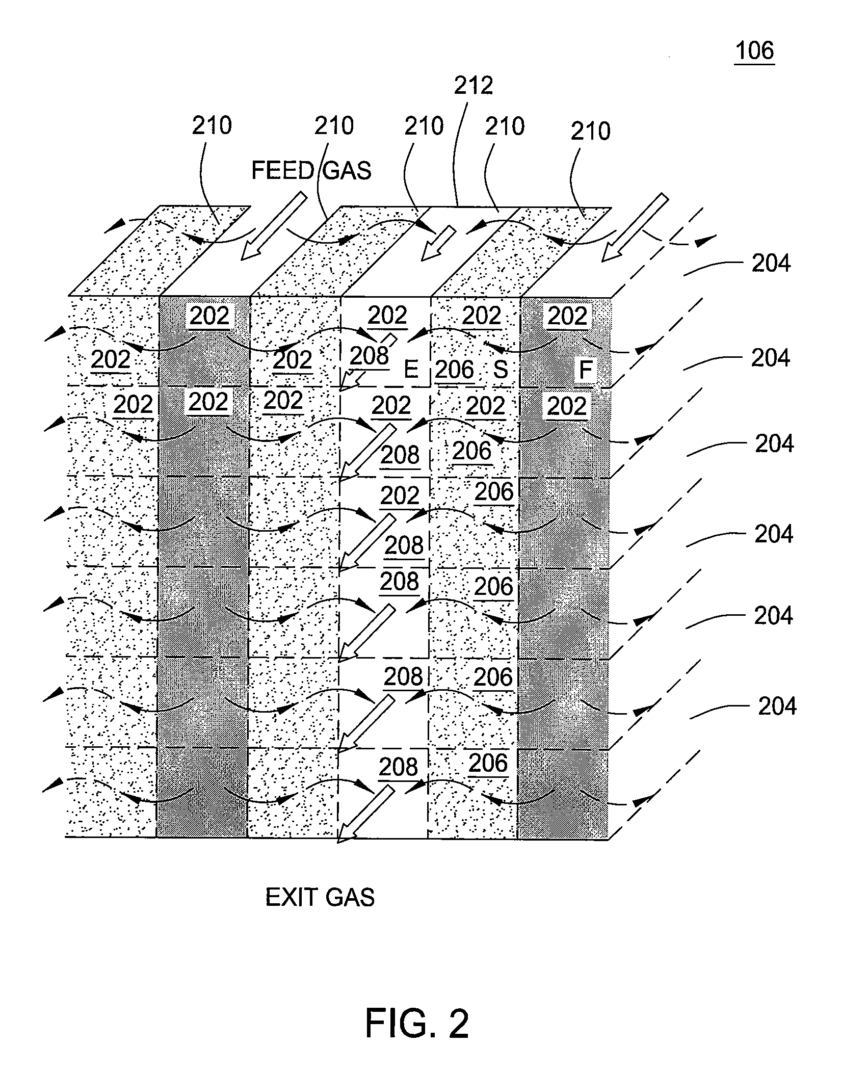
[0006]In one embodiment, the present invention relates generally to an apparatus for reversibly sorbing a target gas. The apparatus comprises an inlet, a multi-channel monolith coupled to said inlet, said multi-channel monolith comprising a plurality of channels, each one of said plurality of channels comprises one or more walls, wherein at least one of said one or more walls of at least one of said plurality of channels is porous and wherein one or more of said plurality of channels contain a sorbent and an outlet coupled to said multi-channel monolith.
[0007]In one embodiment, the present invention is directed towards a method for reversibly sorbing a target gas. The method comprises providing a multi-channel monolith comprising a plurality of channels, each one of said plurality of channels comprises one or more walls, wherein at least one of said one or more walls of at least one of said plurality of channels is porous and wherein one or more of said plurality of channels contain a sorbent, passing a gas mixture through said multi-channel monolith to reversibly remove a target gas from said gas mixture via a sorption process and applying a desorption process to remove said target gas from said sorbent.
[0008]In one embodiment, the present invention is directed towards a second embodiment of an apparatus for reversibly sorbing a target gas. The apparatus comprises an inlet, a multi-channel monolith coupled to said inlet, said multi-channel monolith comprising a plurality of channels, wherein each one of said plurality of channels comprises one or more walls and wherein all of said plurality of channels contain a sorbent and an outlet coupled to said multi-channel monolith.

Problems solved by technology

Cryogenics is considered prohibitively expensive, due to the high energy consumption involved in cooling the large mass of gas, with some potential for economic use at very high CO2 gas concentrations of up to 75%.
Most effluent streams contain 10-40% CO2 gas, and therefore cryogenics is not considered economically viable for CO2 gas separation.
However, amine scrubbing is currently used only on a small commercial scale and is poorly scalable to the large scales needed for CO2 gas capture from, for example, power plant emissions; because of its high energy consumption, low capacity, and high capital and operating costs.
Other methods of CO2 gas separation are in development but also suffer from the deficiencies associated with the cryogenics and the amine scrubbing methodologies noted above.
That is, other methodologies in development, such as solvation as with methanol in the Rectisol process for acid gas removal, and membrane separators suffer from low economic viability due to high energy consumption, poor selectivity, low capacity and poor scalability to large commercial scales.

Method used


Image

  • Method and apparatus for gas removal
  • Method and apparatus for gas removal
  • Method and apparatus for gas removal

Examples


Embodiment Construction

[0017]Aspects of the present invention are directed towards a method and apparatus for gas separation. For example, the methods and apparatuses disclosed herein may be used for reversible sorption of specific gases, such as carbon dioxide (CO2), from mixtures of gases. Sorbing may include either adsorption or absorption, as discussed below. Although CO2 is used as an example, it should be noted that the methods and apparatuses disclosed herein may be used for other gases and are not limited only to CO2.

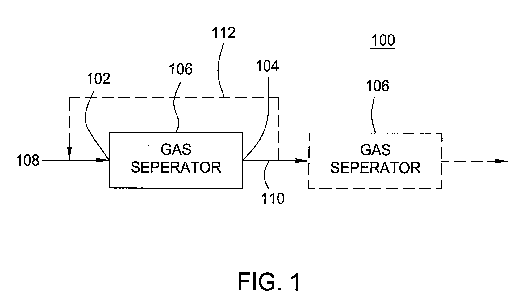
[0018]FIG. 1 illustrates one embodiment of an apparatus 106, e.g. a gas separator 106, in a system 100 for gas separation in accordance with the present invention. The system 100 includes a gas mixture feed 108. The gas mixture feed 108 is fed through the apparatus 106 via an inlet 102 coupled to the apparatus 106. A target gas (e.g., CO2) may be captured within the apparatus 106. The gas mixture less a quantity of the target gas may exit the apparatus 106 via an outlet 104 coupled to...


PUM

PropertyMeasurementUnit
thicknessaaaaaaaaaa
widthaaaaaaaaaa
operating temperaturesaaaaaaaaaa

Abstract

Aspects of the invention include a method and apparatus for reversibly sorbing a target gas. In one embodiment, an apparatus for reversibly sorbing a target gas is disclosed. The apparatus includes an inlet, a multi-channel monolith coupled to the inlet, the multi-channel monolith including a plurality of channels, each one of the plurality of channels includes one or more walls, wherein at least one of the one or more walls of at least one of the plurality of channels is porous and wherein one or more of the plurality of channels contain a sorbent and an outlet coupled to the multi-channel monolith.

Description

FIELD OF THE INVENTION[0001]The present invention relates generally to gas removal and more specifically to a method and apparatus for reversibly sorbing a target gas.BACKGROUND OF THE DISCLOSURE[0002]Gas separation technology is needed in various industries. One gas separation of particular interest is commercial scale carbon dioxide (CO2) gas separation. Currently, there are two methods of CO2 gas separation in commercial use.[0003]One method is cryogenics that involves cooling the entire gas mass to be separated, whereupon the CO2 gas preferentially condenses and is collected. Cryogenics is considered prohibitively expensive, due to the high energy consumption involved in cooling the large mass of gas, with some potential for economic use at very high CO2 gas concentrations of up to 75%. Most effluent streams contain 10-40% CO2 gas, and therefore cryogenics is not considered economically viable for CO2 gas separation.[0004]The second method of CO2 gas separation in commercial use...

Claims


Application Information

Patent Timeline
Patent Type & Authority Applications(United States)
IPC IPC(8): B01D53/02B03C3/68B01D53/32B01D53/30B01D53/047B01D53/14
CPCB01D53/0407B01D2253/102B01D2253/108Y02C10/08B01D2257/504B01D2259/40092B01D2253/20Y02C20/40
Inventor ASARO, MARIANNA F.BLUM, YIGAL
Owner SRI INTERNATIONAL
Learn More