Microelectronics cooling system
a cooling system and microelectronic technology, applied in the field of microelectronic cooling systems, can solve the problems of mechanical complexity and energy-intensive systems, microelectronic devices can generate significant amounts of heat in the course of their operation, and damage electronic components,
- Summary
- Abstract
- Description
- Claims
- Application Information
AI Technical Summary
Benefits of technology
Problems solved by technology
Method used
Image

Examples
example 1
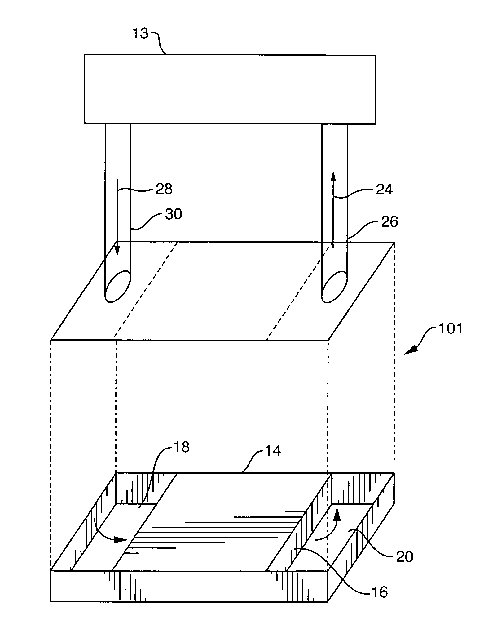
Air-cooled Single-Tube Non-Wick Heat Pipe System
[0061]A heat pipe system is constructed, consisting of a microchannel block-type heat absorber, a finned microchannel heat sink, a connecting pipe, and a working fluid. The heat absorber is an Atotech “Ardex MC-1” microchannel CPU cooler, manufactured by Atotech Deutschland GmbH of Berlin, Germany. One of the two threaded ports is provided with a male adapter ⅜″ tube fitting. The other threaded port is closed off with a pipe plug. The heat sink is an Atotech “Ardex MC-1” microchannel CPU cooler, modified by the addition of thin sheet metal copper cooling fins soldered to the flat side of the MC-1 device. One of the two threaded ports is provided with a male adapter ⅜″ tube fitting. The other threaded port is closed off with a pipe plug. The connecting pipe is a ⅜″ diameter semi-flexible copper or perfluoroalkoxy (PFA) plastic tube, connected to the absorber and heat sink by means of the tube fittings. The connecting pipe is preferably ...
example 2
Air-Cooled Two-Tube Non-Wick Heat Pipe System
[0067]A heat pipe system was constructed, consisting of an Atotech Ardex P microchannel block-type heat absorber, a finned microchannel heat sink, two connecting pipes, and a working fluid. The microchannel heat sink consisted of an Atotech Ardex P microchannel block soldered to a CompUSA Pentium 4 Socket 478 CPU cooler fin-fan assembly. The heat pipe assembly consisted of substantially the same equipment and construction as used in Example 1, with the following differences. The second port of the heat absorber was provided with a ¼″ tube fitting male run tee, in lieu of the pipe plug. The second port of the heat sink was provided with a male adapter ¼″ tube fitting, in lieu of the pipe plug. Two connecting pipes were used. The vapor pipe was a ⅜″ diameter PFA tube, and the liquid pipe was a ¼″ PFA tube. The connecting tubes were connected to the absorber by means of the tube fittings on the heat absorber and the heat sink. The working fl...
example 3
Liquid-Cooled Single-Tube Heat Pipe System
[0071]A heat pipe system is constructed, consisting of a microchannel block-type heat absorber, a water-cooled microchannel heat exchanger heat sink, a connecting pipe, and a working fluid. The heat pipe assembly consists of substantially the same equipment as described in Example 2, with the following differences. The heat sink is a cross-flow 2-fluid microchannel heat exchanger. The working fluid is the first fluid, and flowing cooling water is the second fluid, so that heat is removed from the system by heat transfer from the condensing working fluid vapors, through the walls of the microchannel heat sink, into the cooling water.
PUM
 Abstract
Description
Claims
Application Information
 - Generate Ideas
- Intellectual Property
- Life Sciences
- Materials
- Tech Scout
- Unparalleled Data Quality
- Higher Quality Content
- 60% Fewer Hallucinations
Browse by: Latest US Patents, China's latest patents, Technical Efficacy Thesaurus, Application Domain, Technology Topic, Popular Technical Reports.
© 2025 PatSnap. All rights reserved.Legal|Privacy policy|Modern Slavery Act Transparency Statement|Sitemap|About US| Contact US: help@patsnap.com