Modular cuboidal passive temperature controlled shipping container

a technology of temperature control and shipping container, applied in the direction of domestic cooling apparatus, paper/cardboard articles, lighting and heating apparatus, etc., can solve the problems of difficult transportation of temperature-sensitive goods, high cost, and high cost of temperature control products

Inactive Publication Date: 2010-12-30
PELI BIOTHERMAL LLC (N D GES D STAATES DELAWARE)
View PDF90 Cites 52 Cited by
  • Summary
  • Abstract
  • Description
  • Claims
  • Application Information

AI Technical Summary

Problems solved by technology

The shipment of temperature-sensitive goods is extremely difficult when the shipping container itself is not independently temperature-controlled; ie., does not have an independent power source for maintaining interior temp

Method used


Image

  • Modular cuboidal passive temperature controlled shipping container
  • Modular cuboidal passive temperature controlled shipping container
  • Modular cuboidal passive temperature controlled shipping container

Examples


Embodiment Construction

Nomenclature

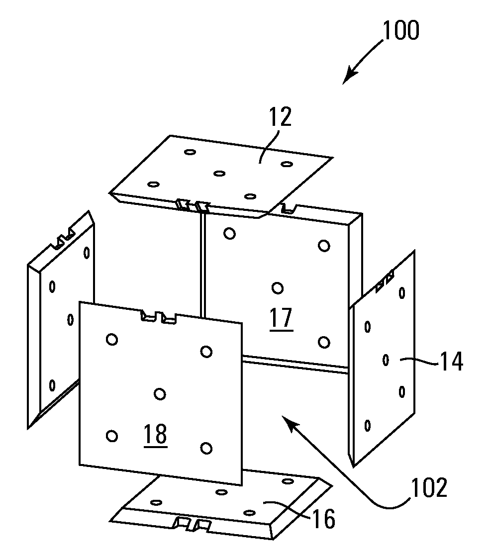
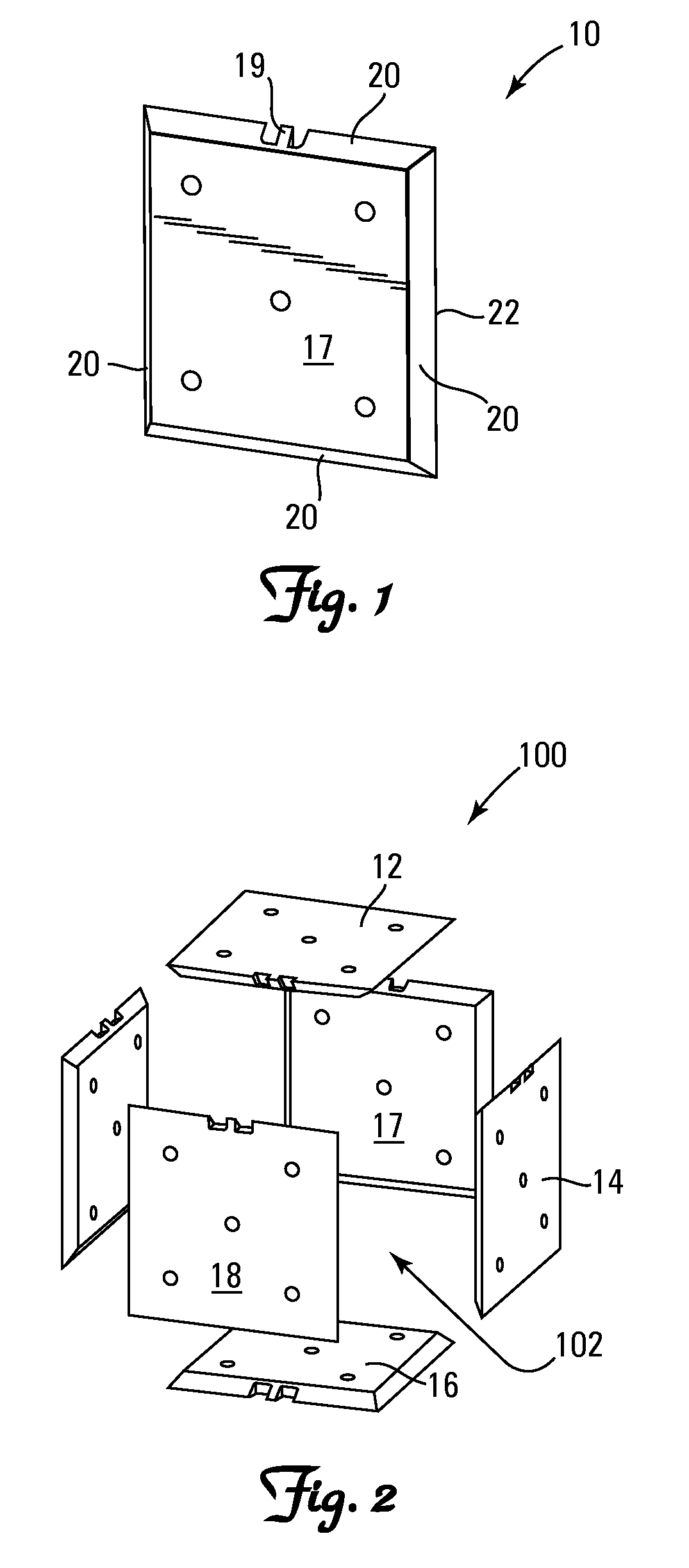
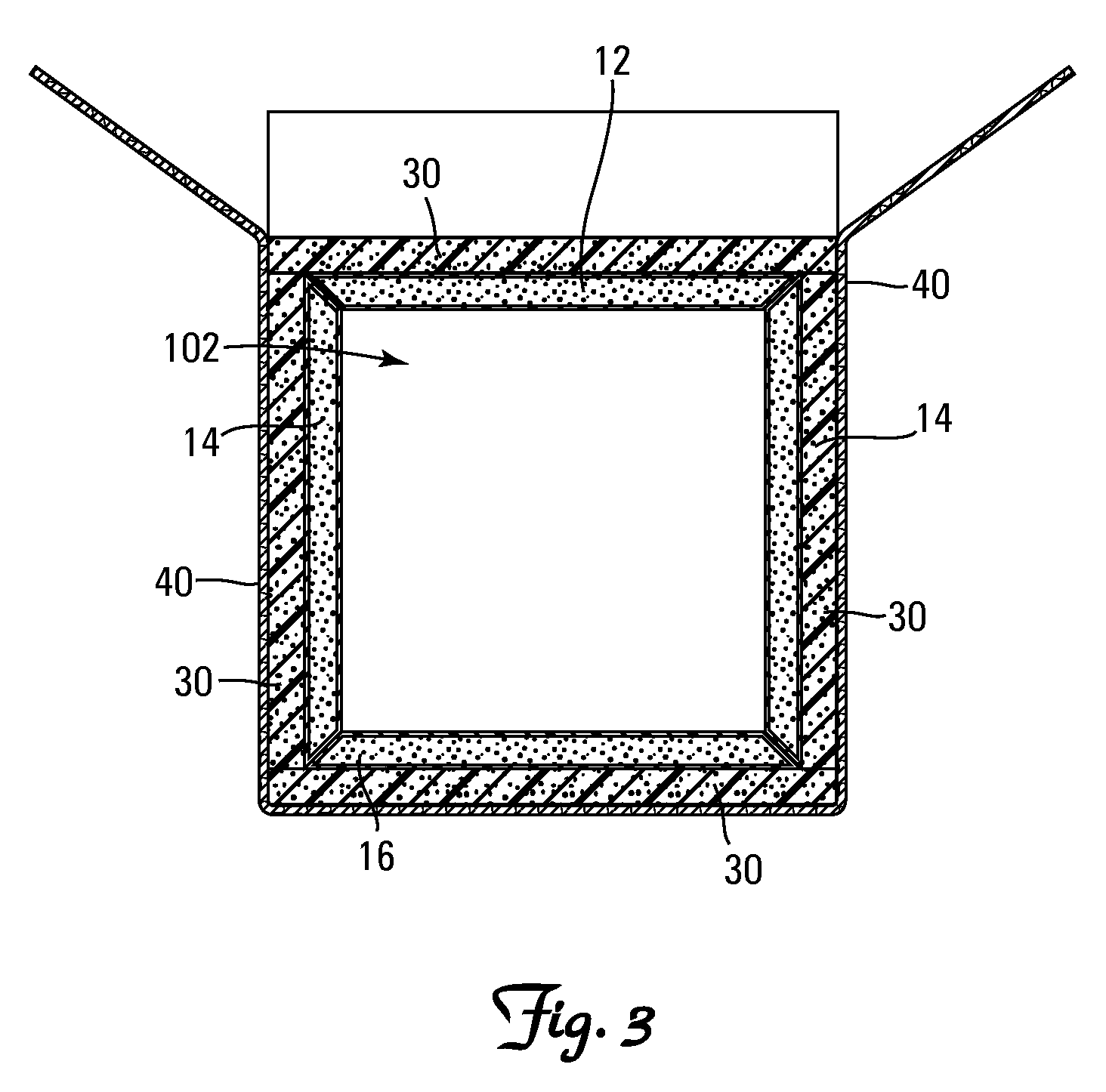
[0009]10 Phase Change Material-Containing Panel[0010]12 Top Phase Change Material-Containing Panel[0011]14 Side Phase Change Material-Containing Panel[0012]16 Bottom Phase Change Material-Containing Panel[0013]17 Inner Surface of Phase Change Material-Containing Panel[0014]18 Outer Surface of Phase Change Material-Containing Panel[0015]19 Fill Port Collar (Pinched and Sealed)[0016]20 Beveled Side[0017]22 Panel Edge[0018]30 Thermal Insulation Panels[0019]40 Outer Shell[0020]100 Thermal Insulating Enclosure[0021]102 Thermal Controlled Interior Volume

Construction

[0022]Referring to FIGS. 1-3 the invention is directed to a thermal insulating enclosure 100 comprising a plurality of separate and distinct phase change material-containing panels 10 (hereinafter “PCM panels”) all configured and arranged to form a retention chamber 102. The PCM panel 10 is a frustum of a right pyramid and all four edges 22 of the top 12, bottom 16 and side panels 14 are 45° angles or bevels 20.

[002...


PUM

PropertyMeasurementUnit
Angleaaaaaaaaaa
Volumeaaaaaaaaaa
Thermal propertiesaaaaaaaaaa

Abstract

A kit comprising a plurality of separate and distinct identically sized phase change material-containing panels shaped as a frustum of a right pyramid, a method of assembling a thermal insulating enclosure from such panels and the resultant assembled thermal insulting enclosure.

Description

BACKGROUND[0001]The shipment of temperature-sensitive goods is extremely difficult when the shipping container itself is not independently temperature-controlled; ie., does not have an independent power source for maintaining interior temperatures within close parameters. Of course, if it is merely desired to maintain an object to be shipped at a nominally cooled temperature—relative to the ambient exterior temperature—a common practice is to pack a shipping container with ice, and hope that the ice will remain in a frozen state during transit so that the object shipped will arrive at its destination still cooled below ambient temperature. This can be an adequate technique for shipping objects where temperature control is not critical. However, even in this case, the temperatures at different points inside the shipping container will vary widely, with parts of the interior of the container becoming quite cool, and other parts of the interior warming to various degrees, depending on ...

Claims


Application Information

Patent Timeline
IPC IPC(8): B65D81/38B23P11/00
CPCB65D81/3825F25D3/08F25D23/063F25D2201/14F25D2303/0831Y10T29/49826F25D2331/804F28D20/02F28D2020/0065Y02E60/145F28F2270/00F25D2323/061Y02E60/14B31D5/0086B65D81/3813
Inventor MAYER, WILLIAM T.CORDER, JACOB
Owner PELI BIOTHERMAL LLC (N D GES D STAATES DELAWARE)
Why Eureka
Try Eureka