Smart boom tip assembly

Active Publication Date: 2010-12-30
EADS CONSTRS AERONAUTICAS
View PDF9 Cites 5 Cited by
  • Summary
  • Abstract
  • Description
  • Claims
  • Application Information

AI Technical Summary

Benefits of technology

[0018]c) Processing said digital signals for obtaining and sending control signals to the ruddevator actuators for moving the ruddevators in order to minimize the loads on the boom.
[0019]One advantage of this invention in that the modular assembly of the boom tip region provides a safer, more maintainable, and more durable refueling apparat

Problems solved by technology

These stresses can result in boom or receptacle failure.
One disadvantage of this device is that it is not properly integrated in the boom.
One disadvantage of this passive coil signals are the maintenance needs of the coil equipment.
Another disadvantage is the potential for damage to the coil since the refueling boom adjacent to the coil installation commonly contacts the receiver aircraft.
Known refueling booms do not prov

Method used


Image

  • Smart boom tip assembly
  • Smart boom tip assembly
  • Smart boom tip assembly

Examples


Embodiment Construction

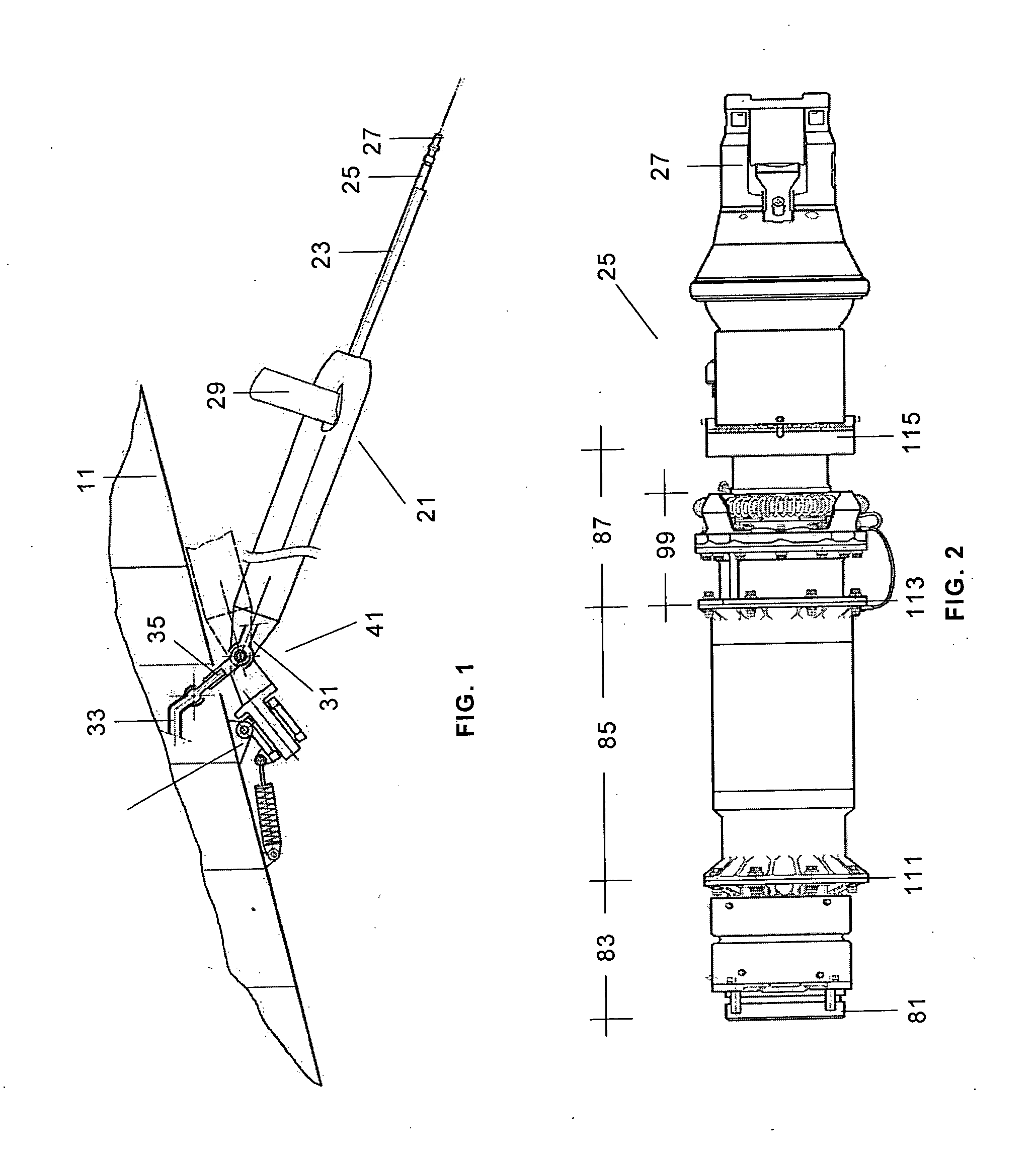
[0027]An aircraft refueling boom 21 is a telescoping beam fuel-tight unit attached to its forward end to the underside fuselage tail of an aircraft 11 by means of a mechanical articulation 41. Integrally attached to the boom 21 are aerodynamic lift surfaces 29 called ruddevators which are used to aerodynamically control the position of the boom 21 in elevation and azimuth.

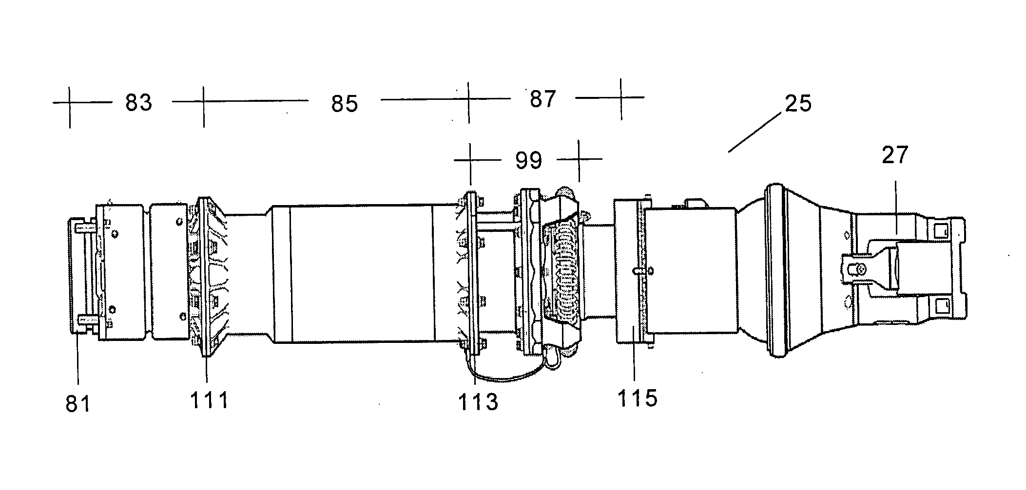
[0028]The outer end portion 23 of the boom 21 is a telescoping section for inward and outward movement. Located on the distal end of the telescoping tube 23 is a boom tip assembly 25 and a nozzle 27. The receiver aircraft, not shown, is equipped with an aerial refueling receptacle which engages with the nozzle 27 for the refueling operation.

[0029]In order to satisfy the refueling space envelope requirements (with respect to the tanker aircraft reference axes), the boom 21 incorporates at is union with the tanker aircraft 11 a mechanical articulation 41 that provides it with two degrees of freedom and, in particular...


PUM


Abstract

A refueling apparatus for interconnecting a tanker aircraft (11) with a receiver aircraft in flight comprising a boom (21) joined to said tanker aircraft (11) by means of a mechanical articulation (41) having control means including a central computer station, an inner fuel conduit, a refueling nozzle (27) at its distal end and, and a smart tip assembly comprising a first module (83) having load sensing means, a second module (85) having load alleviation means and a third module (87), joined to the nozzle (27), having a mechanical fuse (99) for allowing the safe separation of tanker and receiver aircraft in the event of overloads. The invention also comprises a method of load alleviation for minimizing the loads on the boom (21).

Description

FIELD OF THE INVENTION[0001]The present invention relates generally to aircraft refueling booms and more specifically to a boom having a boom tip assembly that provides a load attenuation, limitation and alleviation during tanker / receiver contact and connection.BACKGROUND[0002]An aircraft refueling boom is a beam fuel-tight unit attached to its forward end to a tanker aircraft having aerodynamic lift surfaces called ruddevators used to aerodynamically control the position of the boom in elevation and azimuth that provides a fuel passage from the tanker to the boom nozzle.[0003]The outer end portion of the boom is a telescoping section for inward and outward movement.[0004]The receiver aircraft is equipped with an aerial refueling receptacle which engages with the boom nozzle for the refueling operation.[0005]The boom operator located in the tanker aircraft guides the boom so as to line the boom nozzle with the receiver aircraft receptacle. When the boom nozzle is aligned with the re...

Claims


Application Information

Patent Timeline
IPC IPC(8): B64D39/06
CPCB64D39/04B64D39/00
Inventor DE MIGUEL, MARIANO ORTEGAORCHE, ANTONIO SAN JOSE
Owner EADS CONSTRS AERONAUTICAS
Why Eureka
Try Eureka