

Safety device and power converter
a safety device and power converter technology, applied in the direction of electrical equipment, process and machine control, instruments, etc., can solve the problems of motor stoppage, no consideration is given to configuring a safety device, and inability to operate or malfunction, so as to reduce development costs, prevent non-operation or malfunction of safety functions, and efficiently realize safety functions
- Summary
- Abstract
- Description
- Claims
- Application Information
AI Technical Summary
Benefits of technology
Problems solved by technology
Method used
Image

Examples
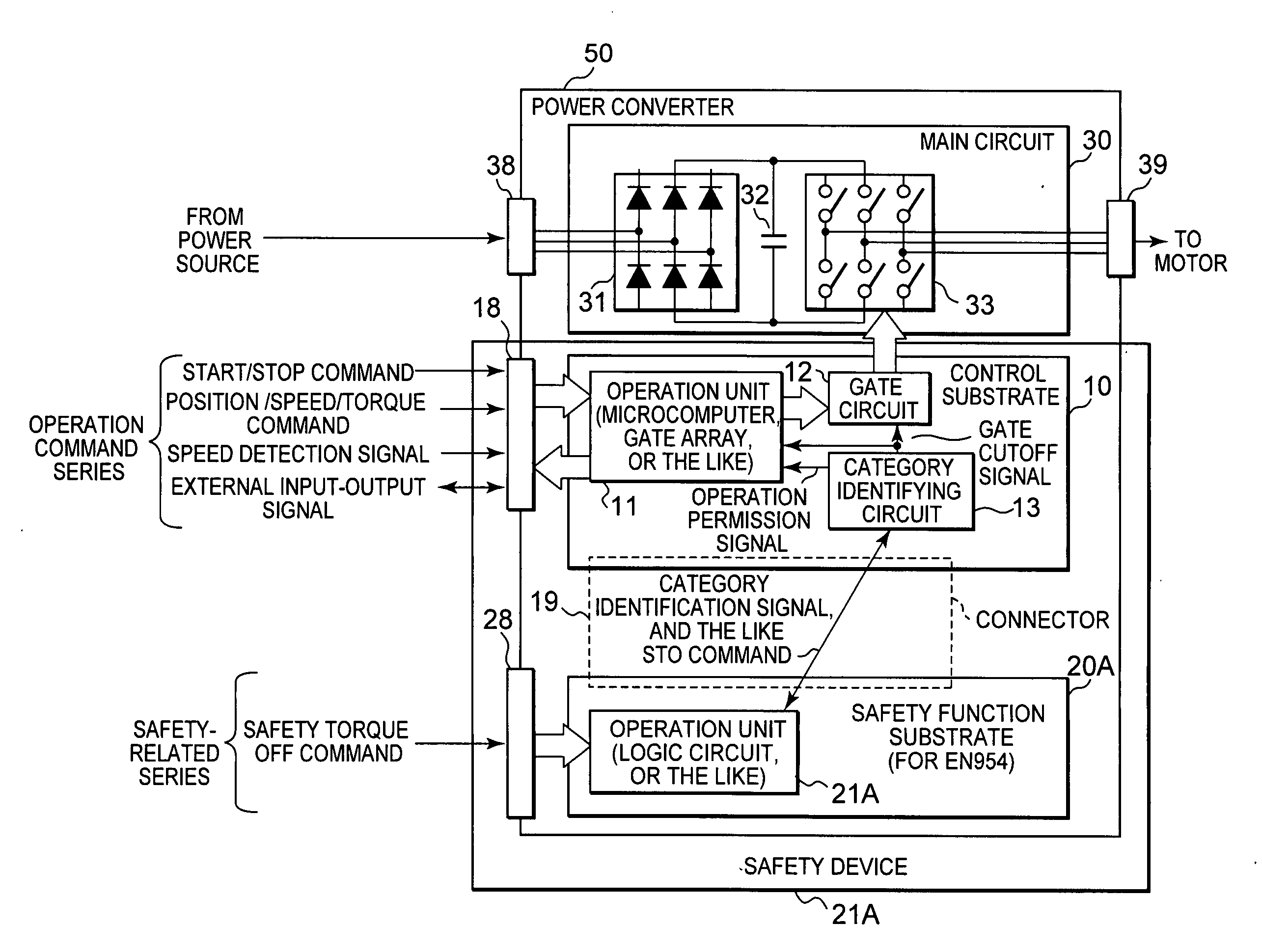
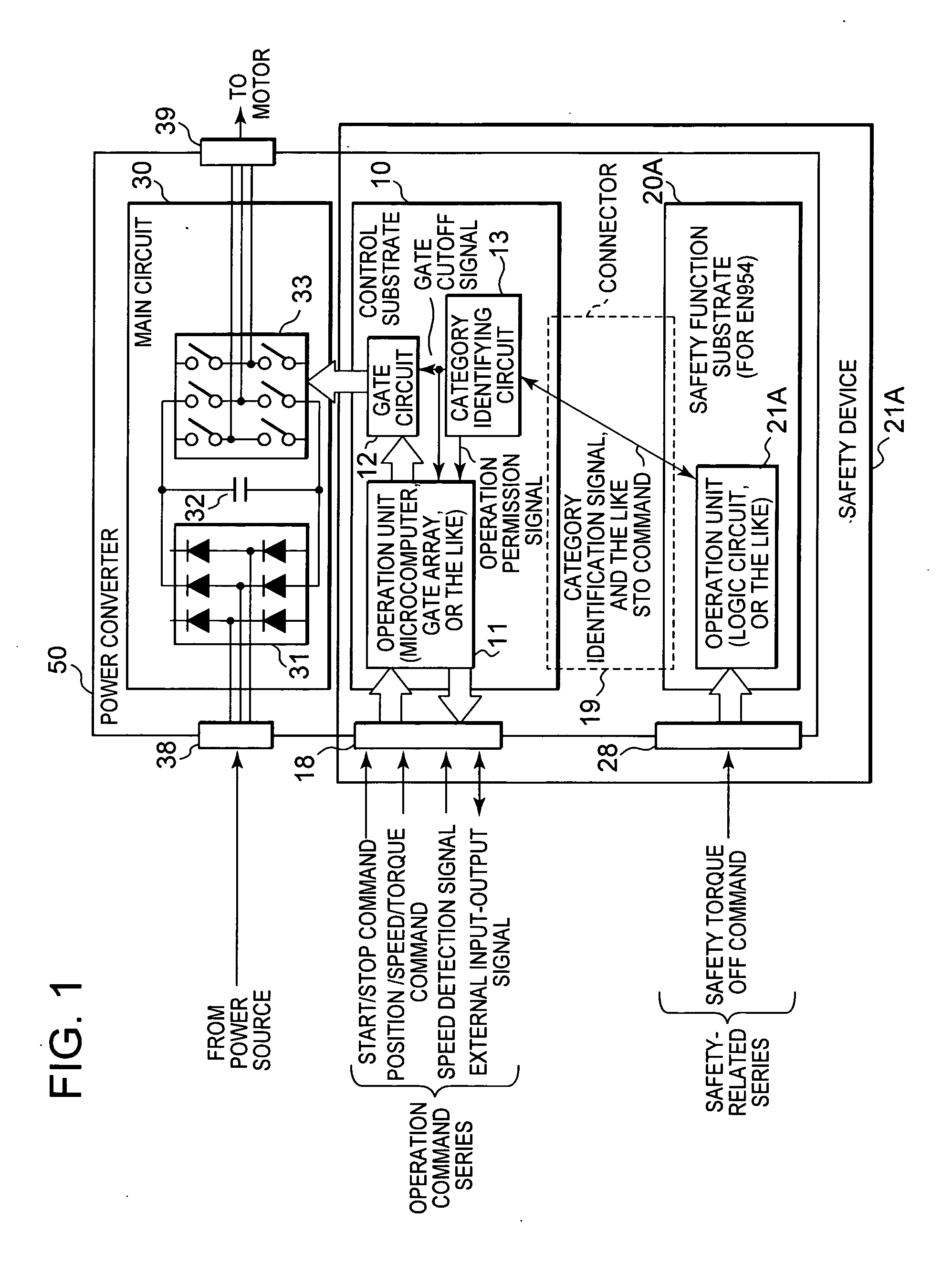
working example 1
[0059]Next, using FIG. 3, a description will be given of the category identifying circuit 13 according to a working example 1 of the safety device 1 with the heretofore described substrate configuration. The category identifying circuit 13 according to the working example transmits and receives, via a designated line, a square wave continuous signal as a signal for identifying the category transmitted by the control substrate 10. In the working example, a case in which a return signal received by the control substrate 10 is of a cycle twice that of a transmitted signal (that is, a cycle of the return signal is twice as long as a cycle of the transmitted signal) is determined to mean that an appropriate substrate is connected.
[0060]Hereafter, an operation of the category identifying circuit 13 will be described in detail. The control substrate 10, firstly, transmits a signal generated by a square wave generator 61 to the safety function substrate 20A. The signal acts as a reference s...
working example 2
[0069]FIG. 9 is an example of a circuit when a case in which the return signal received by the control substrate 10 is of a cycle four times that of the transmission signal is defined as meaning that an appropriate safety function substrate is connected.
[0070]The category identifying circuit 13 shown in FIG. 9 is such that the return signal with a cycle twice that of the transmission signal in the circuit configuration of FIG. 3 is now a return signal with a cycle four times that of the transmission signal. The operation unit 21B of the safety function substrate 20B generates a signal with a cycle four times that of the received reference signal with T flip-flops 91B and 92B, and outputs it as a return signal. The category identifying circuit 13, on receiving the return signal, holds four clocks worth of signals with D flip-flops 71 to 74, and determines, with a coincidence determination circuit 76, whether or not outputs (D, E, F, and G) of each flip-flop coincide. The coincidence ...
working example 3
[0074]FIG. 12 is a working example wherein it is possible to select a safety function substrate with a switch mounted on the control substrate 10, and determine whether or not the correct safety function substrate is mounted.
[0075]The difference with FIG. 9 is that a selection circuit 78 is provided on the input side of the coincidence determination circuit 76. The coincidence determination circuit 76 determines whether or not the desired safety function substrate is mounted by changing the signal pattern to be used for the determination in accordance with a selection signal output from the selection circuit 78.
[0076]FIG. 13A is an example of a circuit configuration of the coincidence determination circuit 76 and selection circuit 78 according to the embodiment. The selection circuit 78 is configured of a switch 82 and a pull-up resistor 81. Because of this, when the switch 82 is turned off, “H” is input into an address A10 of the coincidence determination circuit 76, and when the s...
PUM
 Abstract
Description
Claims
Application Information